Optical methods for real time monitoring of tissue treatment

a tissue treatment and optical method technology, applied in the field of medical technology, can solve the problems of difficult or impossible tracking of tissue treatment progress, undesired tissue modification (e.g., collagen denaturation of a specific area), and the extent of desired tissue modification (e.g., damage to adjacent tissues, etc.) are difficult or impossible to track, and the lack of real time monitoring of such modifications is even more problemati

Inactive Publication Date: 2010-01-21
ALPHA ORTHOPAEDICS
View PDF16 Cites 22 Cited by
  • Summary
  • Abstract
  • Description
  • Claims
  • Application Information

AI Technical Summary

Benefits of technology

[0020]In certain embodiments herein, the methods can monitor the effect of any of a number of different treatments to a biological structure. Such treatments can include, but are not limited to, e.g., applicatio...

Problems solved by technology

A major challenge in modern medicine concerns the controlled treatment of biological tissues through application of temperature change.
While thermotherapy and related treatment regimes have the potential for wide ranging application, they also, however, have the disadvantage in that it is difficult to track their progress.
In other words, the extent of desired t...

Method used


Image

  • Optical methods for real time monitoring of tissue treatment
  • Optical methods for real time monitoring of tissue treatment
  • Optical methods for real time monitoring of tissue treatment

Examples


example 1

Measurement of DoLP and θ

[0171]The instrument configuration diagrammed in FIG. 3 was used to perform measurements on several sample types (i.e., mirror, half wave plate, and bovine tendons). In FIG. 3 the system components comprise: detector D (a silicon photodiode with built-in trans-impedance amplifier), lens L (having a 1″ diameter and 75 mm FL), lock-in amplifier LIA (With reference to source modulation. As described below, the source is modulated at 1 kHz. This modulation signal is also supplied as a reference signal for the lock-in amplifier.), mirror M1 (0.5″ diameter round), mirror M2 (0.5″ diameter round), mirror M3 (1.0″ diameter D-shaped), polarizer P1 (source polarizer), polarizer P2 (source polarizer), parabolic mirror PM (90 degree off-axis), laser source S (808 nm, 200 mW, 1 kHz, square-wave modulated), and sampling lens SL (a split lens, 1.0″ diameter PCX, 15 mm FL, 1 mm black ABS spacer).

[0172]In the measurements, the input polarization angle was maintained at verti...

example 2

Automated DoLP Measurement

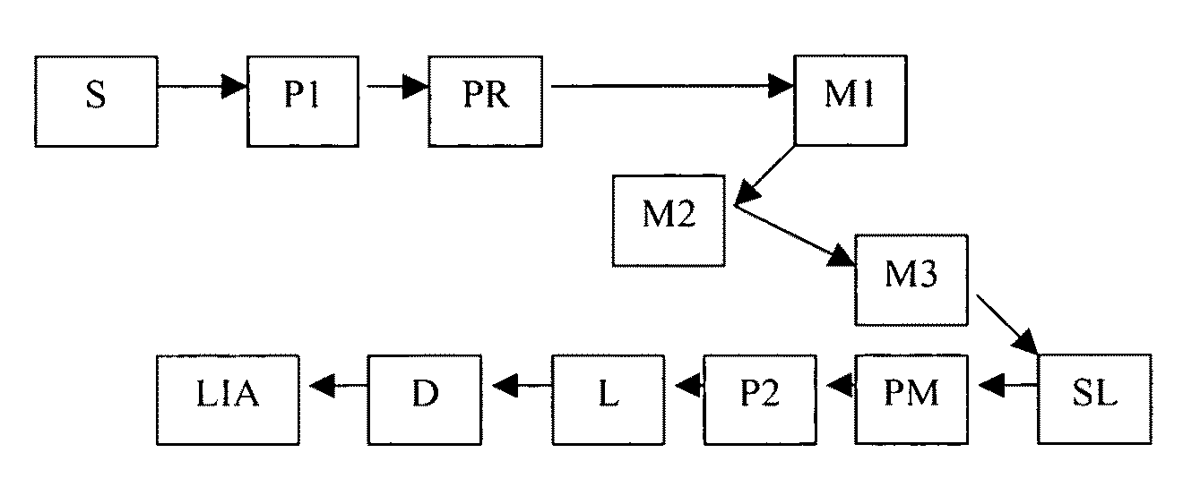
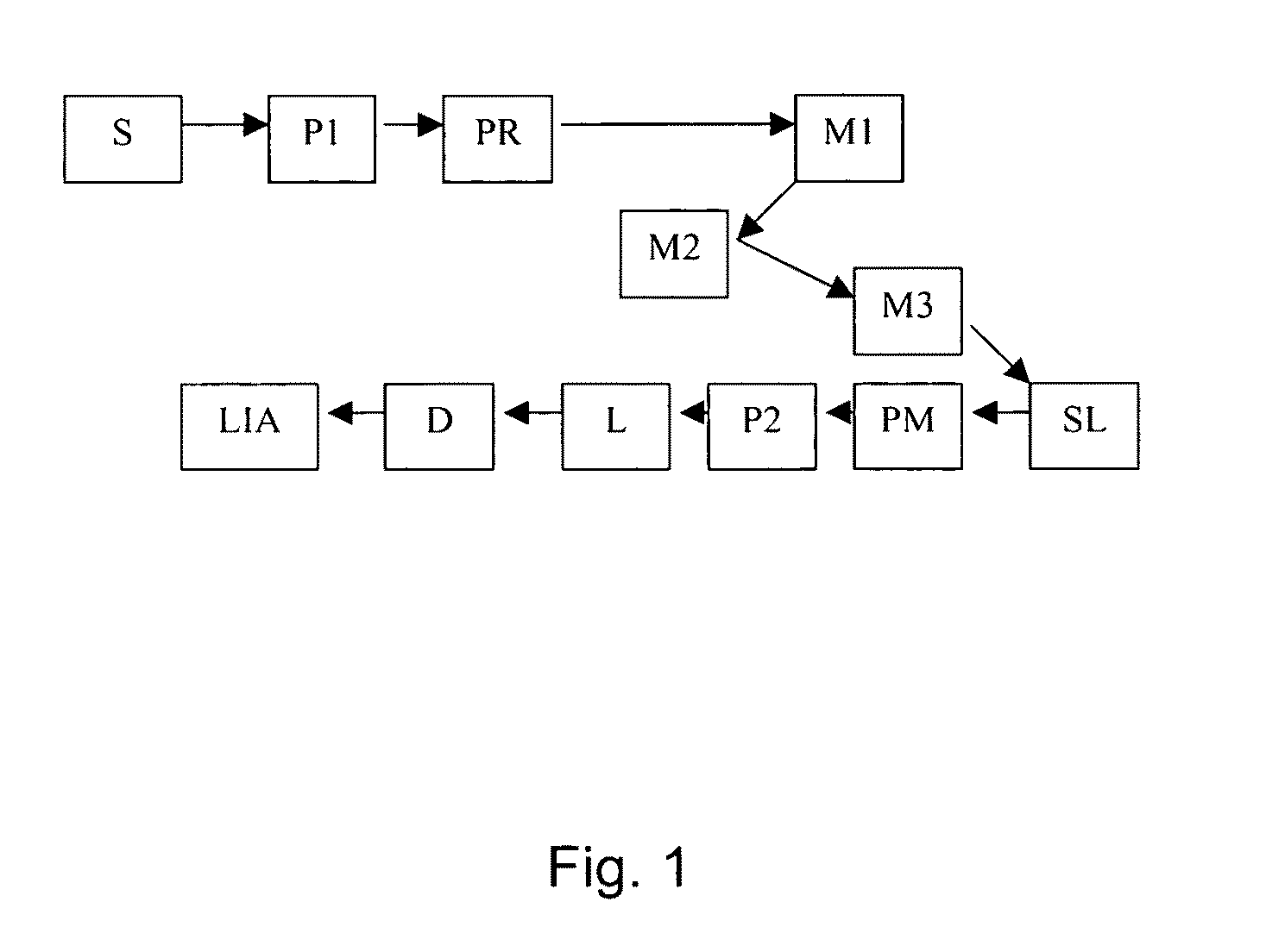
[0177]The instrument outlined in FIG. 7 was constructed to automate collagen birefringence measurement. The arrows in the Figure indicate the direction of the optical beam. The system components in FIG. 7 include: detector D (silicon photodiode with built-in trans-impedance amplifier), lens L (1″ diameter, 75 mm FL), lock-in amplifier LIA (reference to source modulation), mirror M1 (0.5″ diameter round), mirror M2 (0.5″ diameter round), mirror M3 (1″ diameter, D-shaped), polarizer P1 (source polarizer), polarizer P2 (source polarizer), parabolic mirror PM (90 degree off-axis), polarization rotator PR (liquid crystal), rotation stage R (for orienting sample), laser source S (808 nm, 200 mW, 1 kHz, square-wave modulated), and sampling lens SL (split lens, 1″ diameter PCX, 15 mm FL, 1 mm black ABS spacer). As can be seen, the configuration in this Example is similar to that in Example 1, but with the addition of the rotation stage and the polarization rotator....

example 3

Tendon Birefringence Measurements Through Phantom Skin Layers

[0181]Example 3 demonstrates measurement of tendon birefringence through an intervening layer. The ability of measuring birefringence through an intervening layer (e.g., skin) is important in, e.g., non-invasive orthopaedic applications. In this example several skin “phantoms” were tested. These phantom materials included gelatin, Teflon® (DuPont, Wilmington, Del.) and Intralipid® (Kabivitrum, Alameda, Calif.) mixed with gelatin. Gelatin was used because it is composed of denatured collagen, the primary protein constituent found in skin. Teflon was used due to its ready availability in multiple thicknesses and the fact that, like skin, it is highly scattering and weakly absorptive at 808 nm. However, unlike skin, Teflon has little or no natural birefringence. 2% Intralipid in gelatin was used as a phantom mimicking the primary constituents of tissue (water, collagen, and fat) and having similar scattering properties to ski...


PUM


Abstract

The present invention comprises methods and systems/devices for non-invasively measuring baseline collagen and collagen changes during treatment of tissue, e.g., denaturation by the application of RF energy, through linear dichroism, circular dichroism, or birefringence. The invention optionally uses polarization sensitive optical measurements to discriminate between denaturation of unidirectionally oriented strands of collagen, such as a ligament or tendon, and denaturation of planar collagen surfaces, such as the dermal layer of the skin or collagen in joint capsules.

Description

CROSS-REFERENCE TO RELATED APPLICATIONS[0001]This application claims priority to and benefit of U.S. Provisional Patent Application Ser. No. 61 / 066,593, filed on Feb. 20, 2008, the disclosure of which is incorporated herein in its entirety for all purposes.FIELD OF THE INVENTION[0002]The current invention relates to the field of medical technology. More specifically, the present invention provides methods and devices / systems for real time monitoring of tissue treatment, as well as for differentiating between treatment effects on multiple tissue types and / or layers (e.g., unidirectionally oriented collagen and planar collagen).BACKGROUND OF THE INVENTION[0003]A major challenge in modern medicine concerns the controlled treatment of biological tissues through application of temperature change. Numerous medical conditions exist which can optionally be treated through use of such thermotherapy. Such treatments hold special promise for modification of collagen fibers both in planar arran...

Claims


Application Information

Patent Timeline
IPC IPC(8): A61B5/1455A61N7/00A61B18/00A61M31/00
CPCA61B5/0059G01N21/23A61B5/0086A61B5/443A61B5/445A61B5/4523A61B5/4533A61B18/12A61B18/18A61B18/20A61B2017/00057A61N1/403A61N5/0601A61N7/00A61B5/0084
Inventor DEBRECZENY, MARTIN P.VILLEGAS, DIANATAYEB, ABDUL
Owner ALPHA ORTHOPAEDICS
Why Eureka
Try Eureka