Spa having heat pump system

a heat pump and spa technology, applied in the field of spas having heat pumps, can solve the problems of corrosive environment, relatively harsh operating environment of heaters, and known electrical heating units that may not provide the desired degree of efficiency

Active Publication Date: 2010-01-28
BLUE DESERT INT INC
View PDF59 Cites 12 Cited by
  • Summary
  • Abstract
  • Description
  • Claims
  • Application Information

AI Technical Summary

Benefits of technology

[0004]One aspect of the present invention is a spa or hot tub system including a tub having an inner surface defining a tub cavity. The tub is configured to hold sufficient fluid to immerse at least a substantial portion of a user seated in the tub. The tub defines an upper peripheral edge extending around the cavity, and the inner surface of the tub is formed by an inner side wall having an upper portion adjacent the upper peripheral edge. The tub further defines a generally upright side wall forming an outer skirt having an enlarged outer tub surface facing outwardly. The tub defines an interior space between portions of the inner side wall and the outer side wall. The system further includes at least one fluid outlet for exit of fluid from the cavity, and a heat pump system including a water side heat exchanger and an air side heat exchanger. The heat pump system further includes a compressor, and refrigerant conduits fluidly interconnecting the water side heat exchanger and the air side heat exchanger to the compressor, and providing for flow of refrigerant through the water side heat exchanger and through the air side heat exchanger when compressed by the compressor. The water side heat exchanger, the air side heat exchanger, and the compressor may be positioned within the interior space of the tub. The system also includes a water pump and a plurality of fluid conduits fluidly interconnecting the pump to the water side heat exchanger and the fluid inlets and fluid outlet, such that the water pump circulates water from the tub cavity through the water side heat exchanger, such that the water is heated prior to flowing into the tub cavity through the fluid inlets. The system further includes a temperature sensor configured to sense a temperature of water in the tub. A controller is operably connected to the temperature sensor and to the heat pump system, and the controller is configured to control the heat pump system based, at least in part, on the temperature of the water in the tub.

Problems solved by technology

The chemicals and the like added to the water in a spa or hot tub may create a corrosive environment.
The temperature extremes further contribute to creating a relatively harsh operating environment for heaters in such applications.
Also, known electrical heating units may not provide the desired degree of efficiency.
Although such heat pumps have been somewhat successful, they are generally too large and bulky for use in a compact spa / hot tub system.
Furthermore, heat pumps developed for swimming pools are generally not designed to heat the water to higher temperatures as required for a typical spa / hot tub, and may also not be suitable for use in the uniquely harsh environment of a typical spa / hot tub.
Still further, known electrical heaters for spas / hot tubs may have limited power, such that substantial time is required to bring the water in the spa / hot tub up to the desired temperature if the water was cooled after a period of non-use or the like.

Method used


Image

  • Spa having heat pump system
  • Spa having heat pump system
  • Spa having heat pump system

Examples


Embodiment Construction

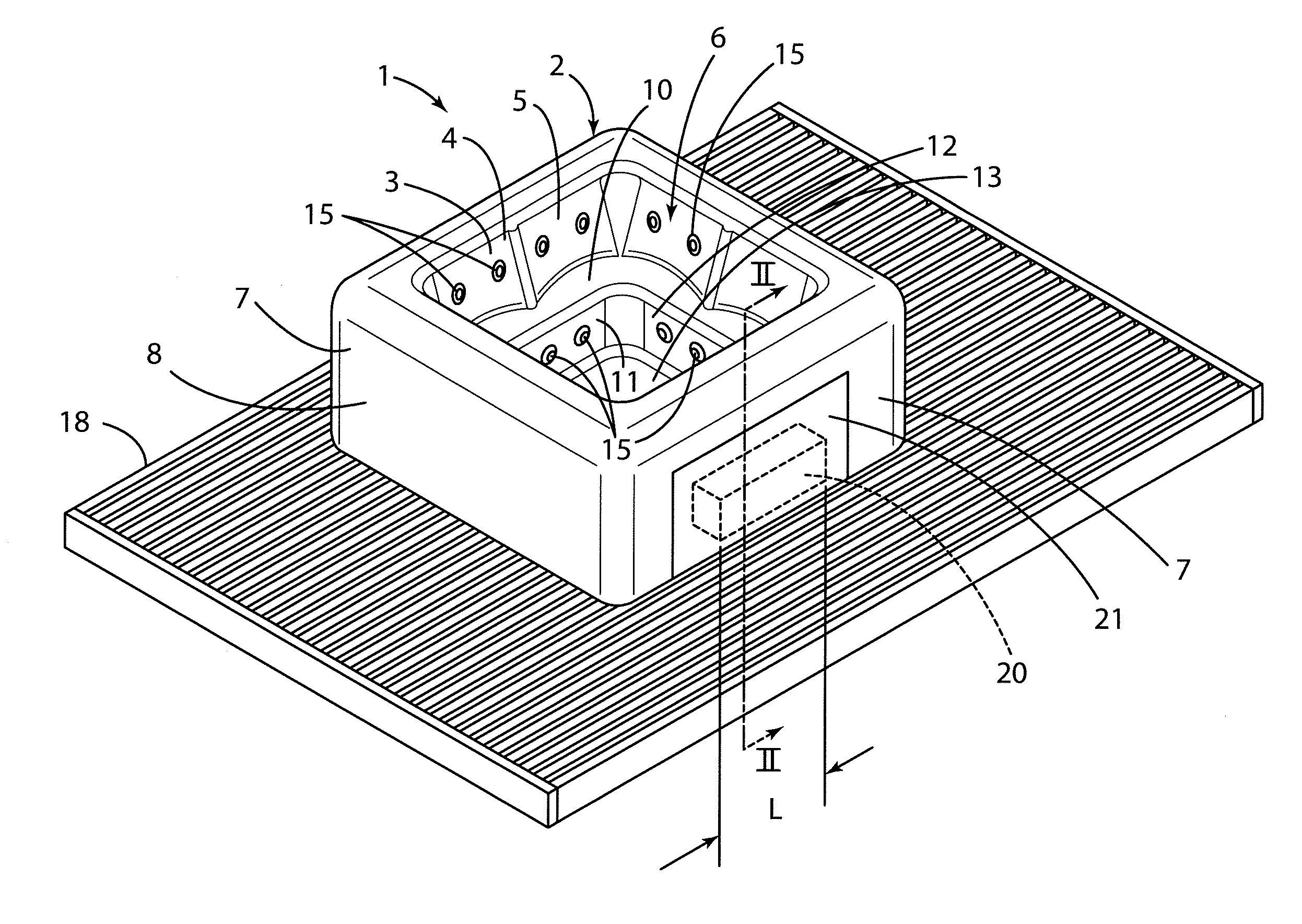
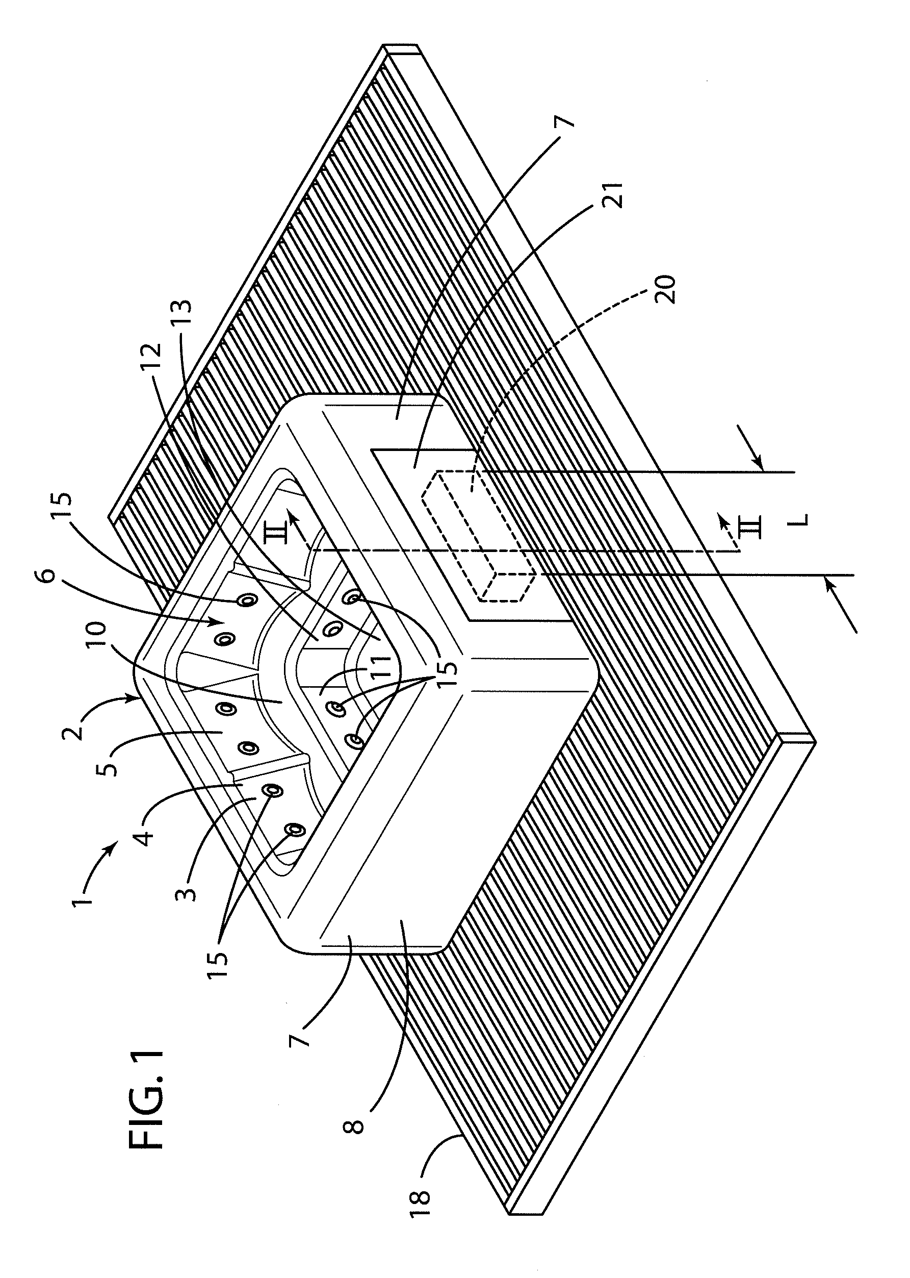
[0012]For purposes of description herein, the terms “upper,”“lower,”“right,”“left,”“rear,”“front,”“vertical,”“horizontal,” and derivatives thereof shall relate to the invention as oriented in FIG. 1. However, it is to be understood that the invention may assume various alternative orientations and step sequences, except where expressly specified to the contrary. It is also to be understood that the specific devices and processes illustrated in the attached drawings and described in the following specification are simply exemplary embodiments of the inventive concepts defined in the appended claims. Hence, specific dimensions and other physical characteristics relating to the embodiments disclosed herein are not to be considered as limiting, unless the claims expressly state otherwise.

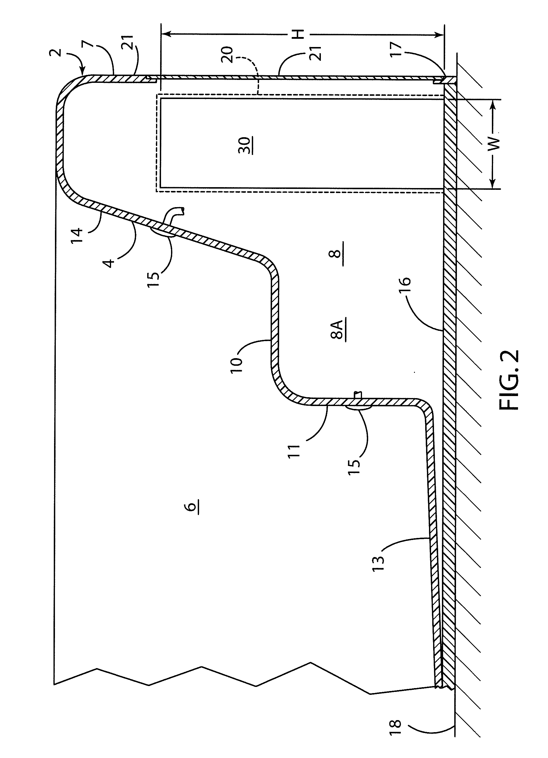
[0013]With reference to FIG. 1, a spa / hot tub system 1 according to the present invention includes a primary structure 2 that may be made of a fiber-reinforced polymer or other polymer material or the l...


PUM


Abstract

A spa or hot tub system includes a tub forming a cavity that holds a fluid such as water therein, and a water circulation system provides for circulation of water within the tub. The hot tub includes inner and outer surfaces, and defines an internal space. A heat pump system is operably connected to the water circulation system, and heats the water in the hot tub. The water side heat exchangers of the heat pump may include a polymer housing, and coiled inner elements for refrigerant. The coils may be made of a corrosion-resistant metal tubing or the like. The system may include a conventional electric heating element in addition to the heat pump to provide additional heating capacity.

Description

CROSS-REFERENCE TO RELATED APPLICATIONS[0001]This is a continuation of International Application PCT / US2008 / 059225, with an international filing date of Apr. 3, 2008. PCT Application No. PCT / US2008 / 059225 claims the benefit of U.S. Provisional Application No. 60 / 909,869, filed on Apr. 3, 2007, entitled SPA HAVING HEAT PUMP SYSTEM. The entire contents of the above-identified International Application and Provisional Application are incorporated herein by reference.BACKGROUND OF THE INVENTION[0002]Various types of heating units for heating water in spas / hot tubs have been developed. One type of known heater utilizes an electrical resistance element that generates heat when electrical current passes through the electrical resistance element. Heat generated by the electrical resistance element is transferred through electrically non-conductive material to the water from the spa / hot tub as it flows through the heater to thereby heat the water in the spa / hot tub. The chemicals and the lik...

Claims


Application Information

Patent Timeline
Patent Type & Authority Applications(United States)
IPC IPC(8): E04H4/00
CPCA61H33/02A61H33/6063F28D7/024F28D7/0066
Inventor THWEATT, JR., CARLISLE
Owner BLUE DESERT INT INC
Why Eureka
Try Eureka