

Integral flow sleeve and fuel injector assembly
a fuel injector and integrated technology, applied in the direction of machines/engines, combustion types, lighting and heating apparatus, etc., can solve the problems of fuel leakage, inadequate structural integrity, and fuel delivery too closely to the liner assembly of the combustion section
- Summary
- Abstract
- Description
- Claims
- Application Information
AI Technical Summary
Problems solved by technology
Method used
Image

Examples
second embodiment
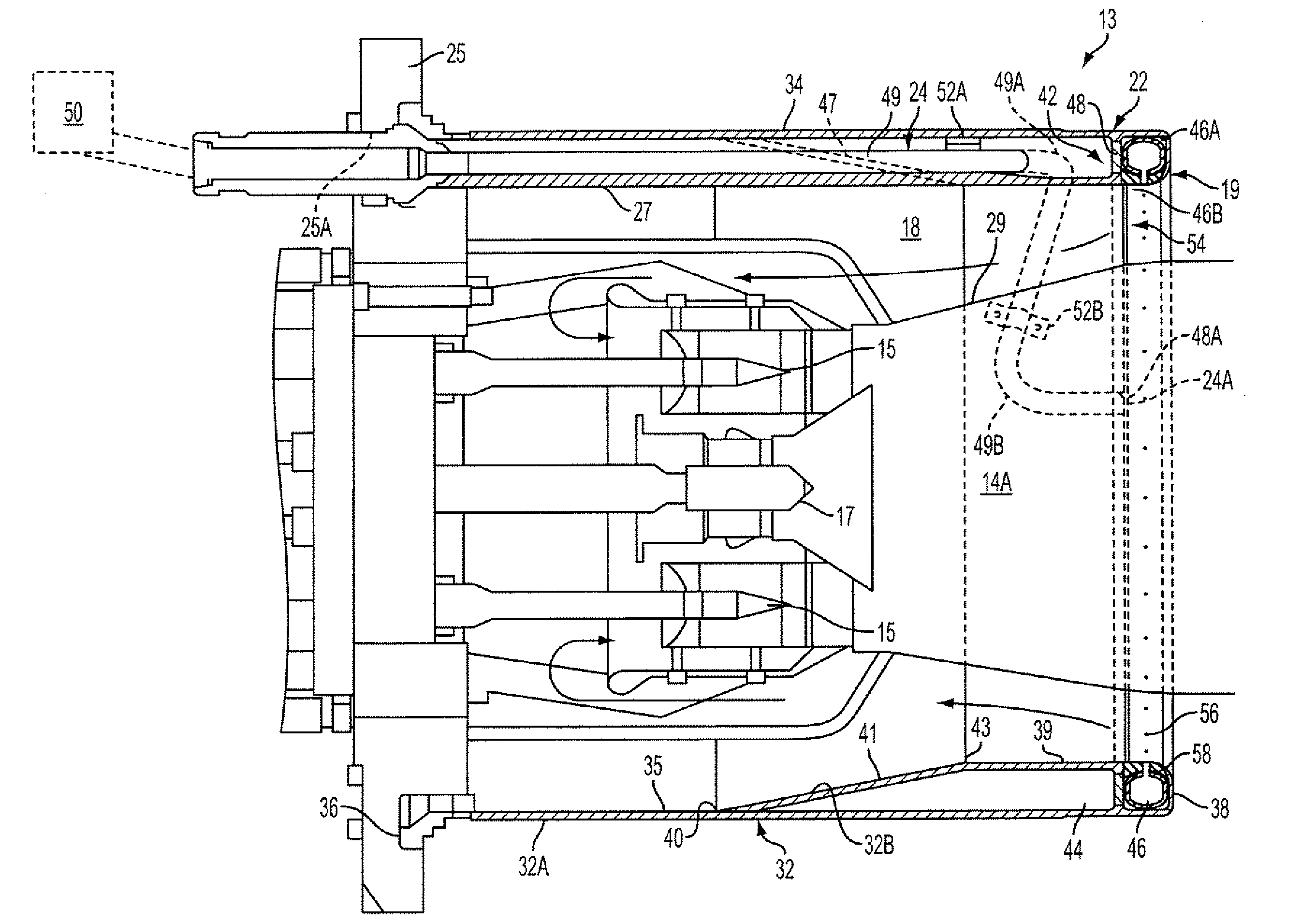
[0033]FIG. 4 illustrates a pre-mix fuel injector assembly 119 according to the invention, wherein elements corresponding to elements of the first described embodiment of the fuel injector assembly 19 (FIGS. 2, 2A and 3) are identified by the same reference numeral increased by 100. In the present embodiment, the fuel injector assembly 119 includes a flow sleeve 122 comprising a sleeve wall 132 defined by a first portion 132A and a second portion 132B. The first portion 132A extends from a forward end (not shown in this embodiment) of the sleeve wall 132 toward an aft end 138 of the sleeve wall 132 and terminates short of the aft end 138. The second portion 132B is mechanically affixed to the first portion 132A at a sleeve wall interface 140 such as by a welded connection 155A, to define the aft end 138 of the sleeve wall 132.
[0034]A cavity or annular fuel supply chamber 146 comprising an annular channel 146A is formed in the sleeve wall 32 proximate the interface 140 between the fir...
third embodiment
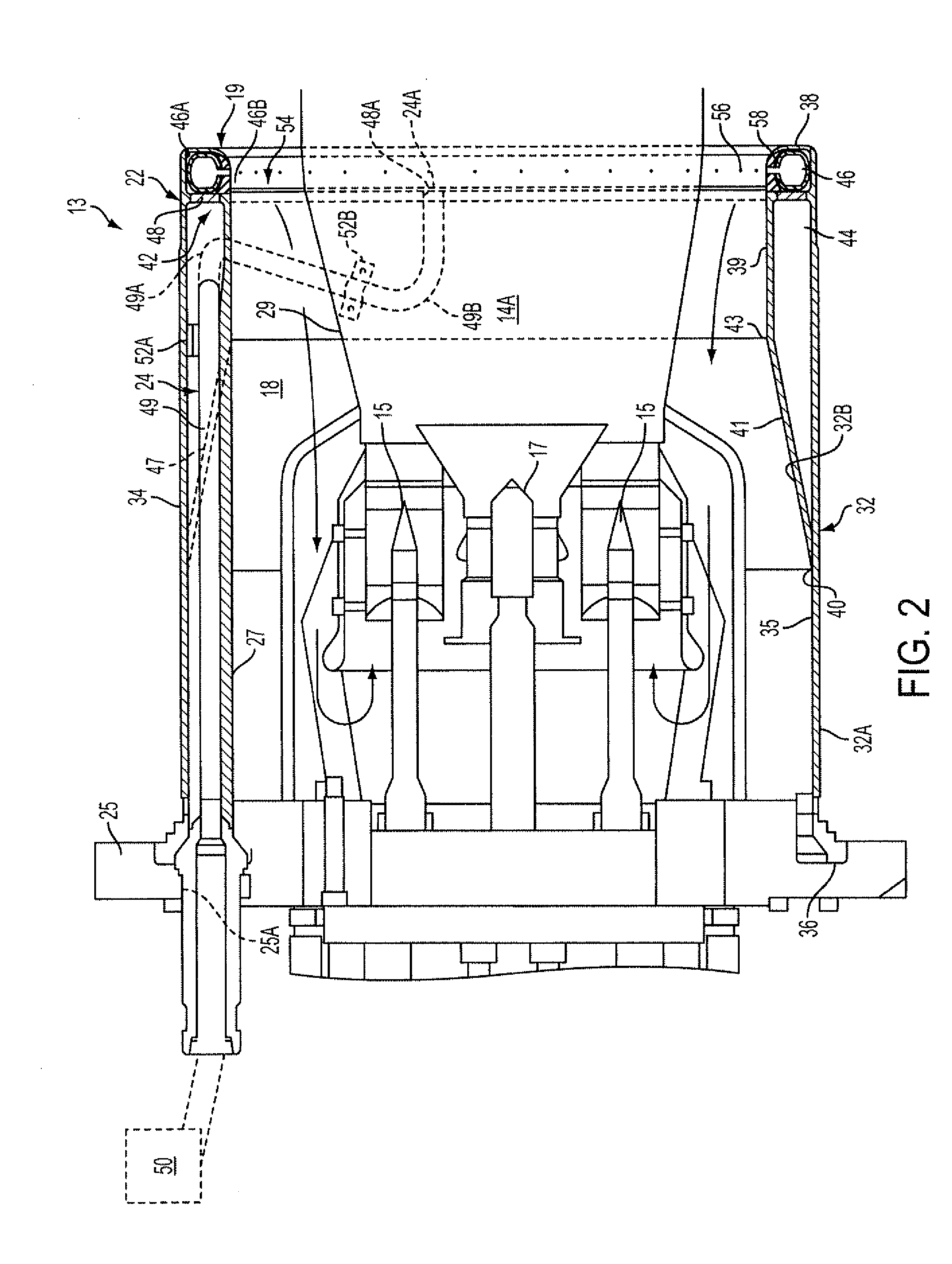
[0037]FIG. 5 illustrates a pre-mix fuel injector assembly 219 according to the invention, wherein elements corresponding to elements of the first described embodiment of the fuel injector assembly 19 (FIGS. 2, 2A and 3) are identified by the same reference numeral increased by 200. In the present embodiment, the fuel injector assembly 219 includes a flow sleeve 222 comprising an annular sleeve wall 232 extending from a forward end (not shown in this embodiment) to an aft end 238. A cavity or annular fuel supply chamber 246 comprising an annular channel 246A is formed in the sleeve wall 232 adjacent to the aft end 238.
[0038]A fuel dispensing structure 254 is associated with the annular channel 246A and, in the present embodiment, comprises an annular segment or cover structure 246B affixed to a radially inner surface 235 of the sleeve wall 232 to cover the annular channel 246A. The cover structure 246B is preferably affixed to the sleeve wall 232 at welds 255A, 255B to create the sub...
PUM
 Abstract
Description
Claims
Application Information