Gas analyzer and method of gas analysis

a gas analyzer and gas analysis technology, applied in the field of gas analyzers, can solve the problems of unpredictability of hazardous and toxic gases present, serious effects of chemical substances in the environment on human beings, and inability to obtain prior information on the kinds of gases present, etc., and achieve the effect of high sensitivity

Active Publication Date: 2010-01-28
BALL WAVE INC
View PDF7 Cites 24 Cited by
  • Summary
  • Abstract
  • Description
  • Claims
  • Application Information

AI Technical Summary

Benefits of technology

[0068]The present invention provides a gas analyzer that can be miniaturized and detect a wide variety of gases with high sensitivity, and also provides a method of gas analysis.

Problems solved by technology

Chemical substances in the environment have serious effects on human beings, and there are many kinds of unpredictable hazardous and toxic gases present in living spaces, production sites, transportation facilities, and other areas.
In most cases, no prior information on the kinds of gases present can be obtained.
It is therefore necessary to separate and detect more than 100 kinds of various hazardous and toxic gases; gas sensors for detection of only several kinds of specific gases are insufficient.
Further, since a gas sensor generally responds to a plurality of gases, a wide variety of gases can hardly be detected even by as many sensors as the number of gases.
However, when several gases reach the sensors at the same time, such methods using pattern recognition problematically fail to detect the gases.
As stated above, the measurement of simultaneously reaching several gases is difficult for portable sensors, but this measurement is possible by analyzers installed on the floor or table.

Method used


Image

  • Gas analyzer and method of gas analysis
  • Gas analyzer and method of gas analysis
  • Gas analyzer and method of gas analysis

Examples


Embodiment Construction

[0076]The following explains embodiments of the present invention with reference to the drawings.

[0077]FIGS. 1 through 6 show gas analyzers and methods of gas analysis according to embodiments of the present invention.

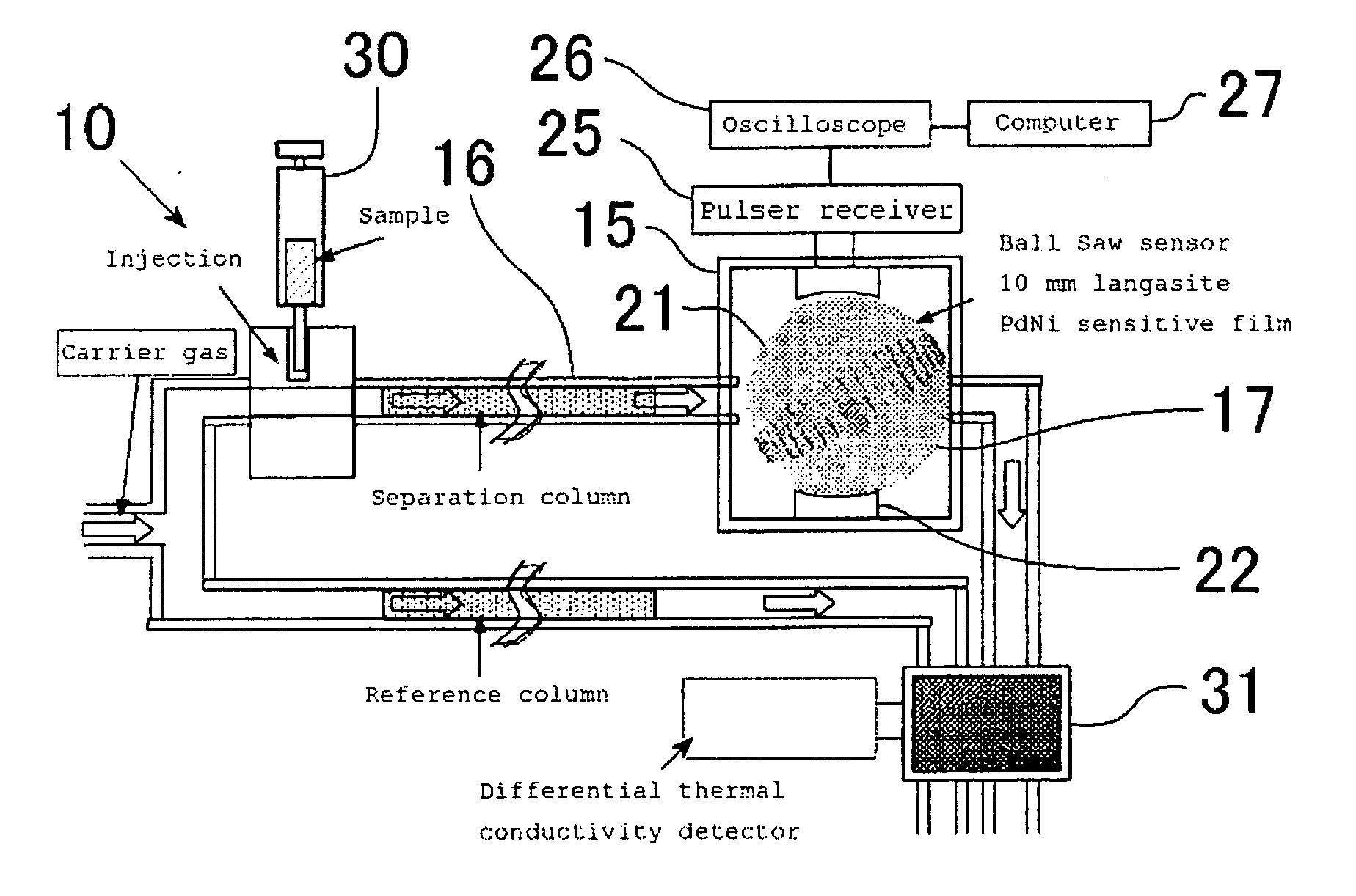
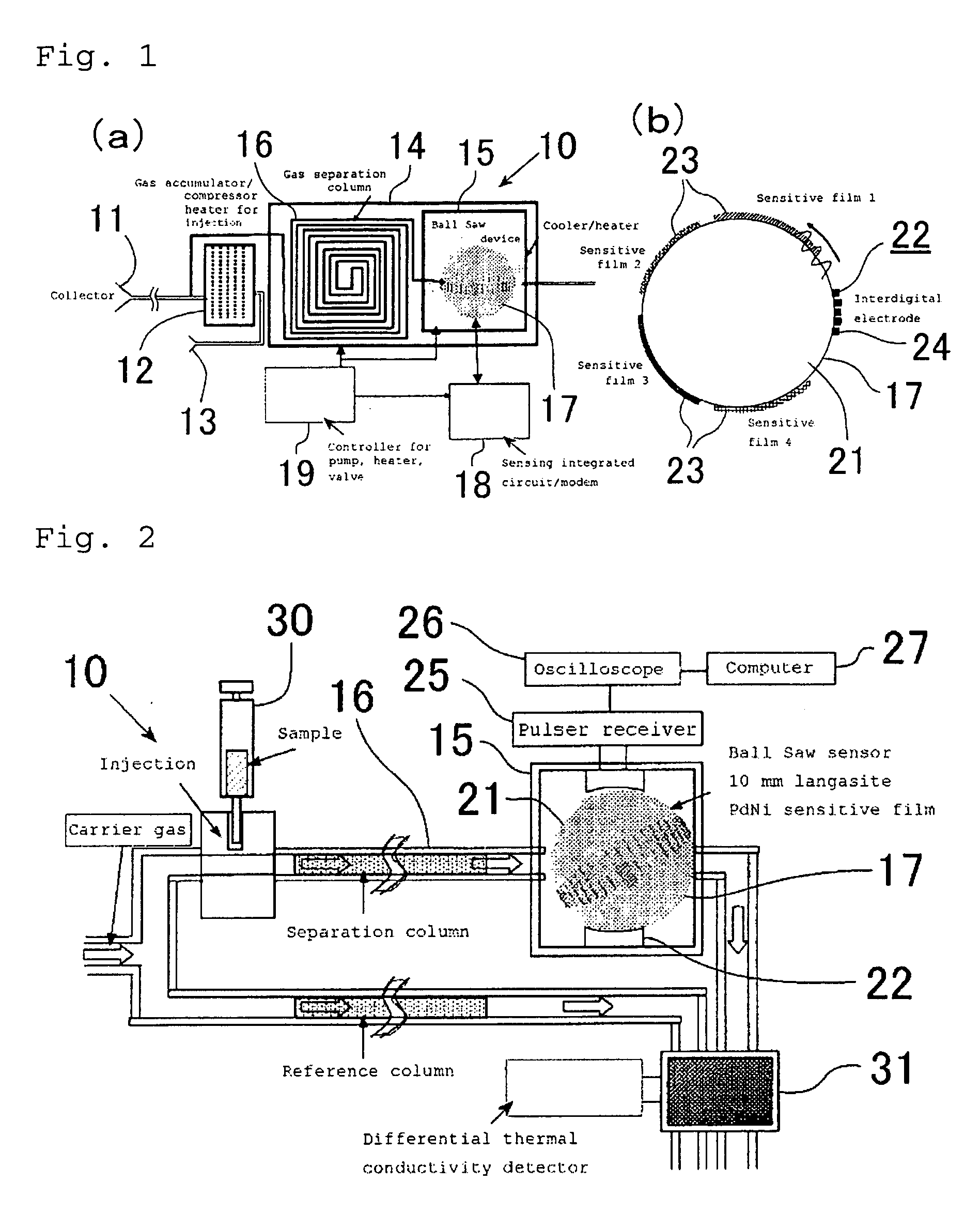
[0078]As shown in FIGS. 1 and 2, a gas analyzer 10 has a collector 11, a compressor 12, a carrier gas supplying part 13, a casing 14, a device housing 15, a separation column 16, a surface acoustic wave device 17, a measuring part 18, and a controller 19.

[0079]As shown in FIG. 1(a), the collector 11 is configured so as to collect a sample gas by aspiration. The collector 11 is connected to the compressor 12, which can compress and store the sample gas aspirated in the collector 11. The compressor 12 has a heater that can heat the stored sample gas. The compressor 12 is connected to the carrier gas supplying part 13, which can supply a carrier gas with a pump into the compressor 12. The device housing 15 is mounted in the inside of the casing 14.

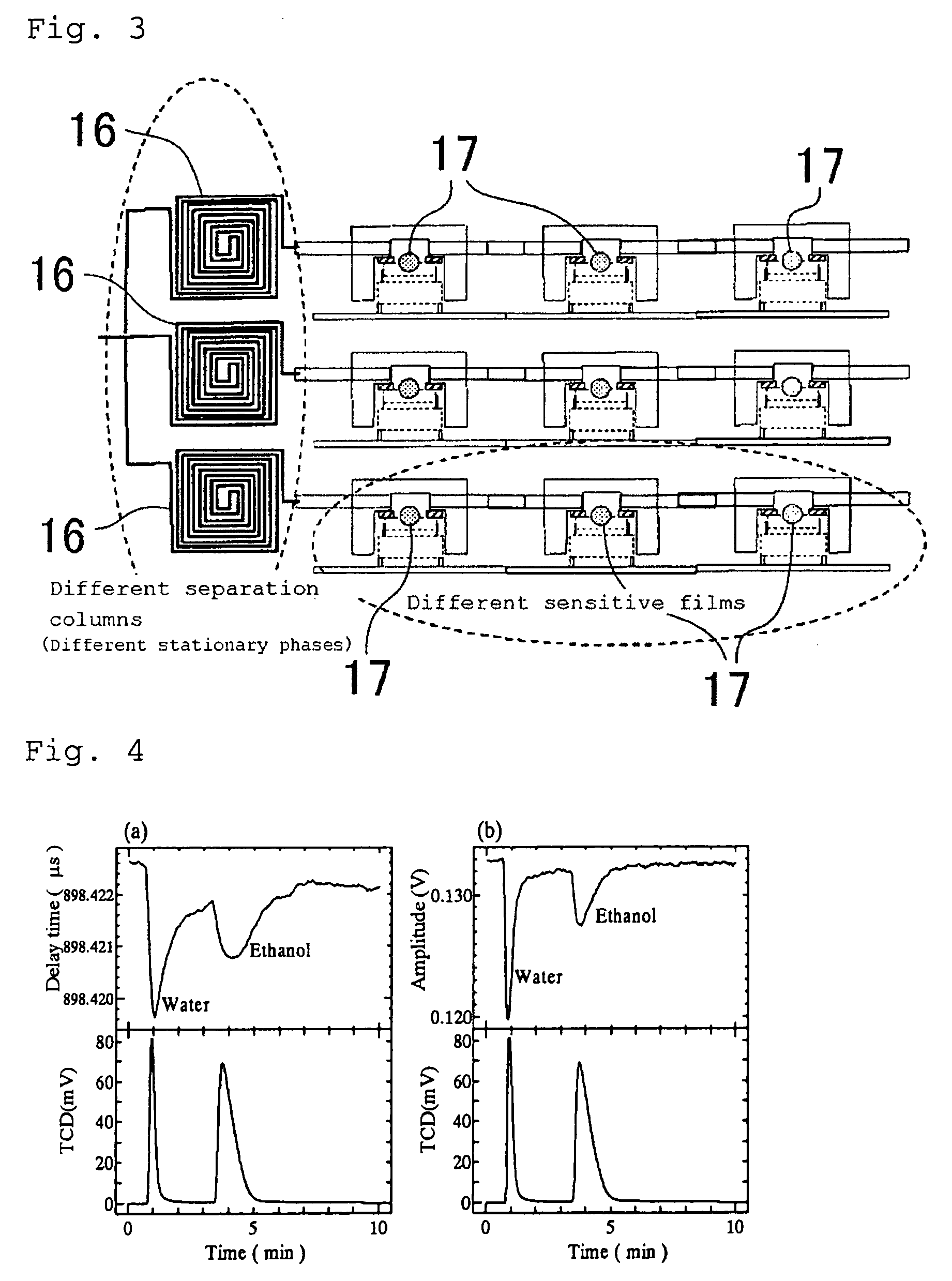
[0080]The separation col...


PUM

PropertyMeasurementUnit
surface acoustic waveaaaaaaaaaa
physical quantityaaaaaaaaaa
surface acoustic wave measuringaaaaaaaaaa

Abstract

The present invention provides a gas analyzer that can be miniaturized and detect a wide variety of gases with high sensitivity, and a method of gas analysis. A separation column 16 is configured so as to pass a sample gas together with a carrier gas through the inside thereof. A surface acoustic wave device 17 has a base material 21 with an annularly continuous annular surface formed of at least apart of a spherical surface; a surface acoustic wave generating means 22 capable of generating a surface acoustic wave that propagates along the annular surface; and a plurality of reaction parts 23 provided along the annular surface so as to change a predetermined physical quantity of the surface acoustic wave in response to the components of the sample gas. The surface acoustic wave device 17 is arranged so that the sample gas passing through the separation column 16 is reacted with the reaction parts 23. The measuring part 18 can measure a physical quantity of the surface acoustic wave propagating along the annular surface, and the components of the sample gas can be analyzed on the basis of the measured physical quantity.

Description

BACKGROUND OF THE INVENTION[0001]1. Technical Field[0002]The present invention relates to a gas analyzer using a surface acoustic wave device, and a method of gas analysis.[0003]2. Background Art[0004]Chemical substances in the environment have serious effects on human beings, and there are many kinds of unpredictable hazardous and toxic gases present in living spaces, production sites, transportation facilities, and other areas. Hence, there is a demand for a sensing technique of immediately measuring such gases by a portable compact sensor and setting off alarm. In most cases, no prior information on the kinds of gases present can be obtained. It is therefore necessary to separate and detect more than 100 kinds of various hazardous and toxic gases; gas sensors for detection of only several kinds of specific gases are insufficient. Further, since a gas sensor generally responds to a plurality of gases, a wide variety of gases can hardly be detected even by as many sensors as the nu...

Claims


Application Information

Patent Timeline
Patent Type & Authority Applications(United States)
IPC IPC(8): G01N23/00
CPCG01N29/022G01N29/024G01N29/032G01N30/76G01N2291/0423G01N2030/765G01N2291/0215G01N2291/0255G01N2291/0256G01N2030/025
Inventor YAMANAKA, KAZUSHITSUJI, TOSHIHIROIWATA, NAOYA
Owner BALL WAVE INC
Why Eureka
Try Eureka