[0009]In the power output apparatus according to this aspect of the invention, in the state of connection of both the first motor and the second motor with the driveshaft by means of the speed change-transmission
assembly to output power to the driveshaft, one of the first motor and the second motor is specified as the main motor. The first motor and the second motor are then controlled to make the main motor preferentially output
power over the other of the first motor and the second motor specified as the auxiliary motor and to ensure output of a power, which is equivalent to the
power demand or the power required for the driveshaft, to the driveshaft. Namely one of the first motor and the second motor specified as the main motor is controlled to output the power of mainly covering the
power demand, while the other of the first motor and the second motor specified as the auxiliary motor is controlled to output the power of filling a deficiency of the
power demand. Such control ensures continuous output of a relatively large torque, while preventing excessive heat evolution in either of the first motor and the second motor and significant decreases of the respective motor efficiencies. The preferential power output by the main motor over the auxiliary motor effectively prevents a variation in power output to the driveshaft due to a difference between the responses of the first motor and the second motor to respective power command values, as well as the occurrence of vibration. In the state of connection of both the two motors with the driveshaft by means of the speed change-transmission
assembly, this arrangement ensures adequate control of the two motors.
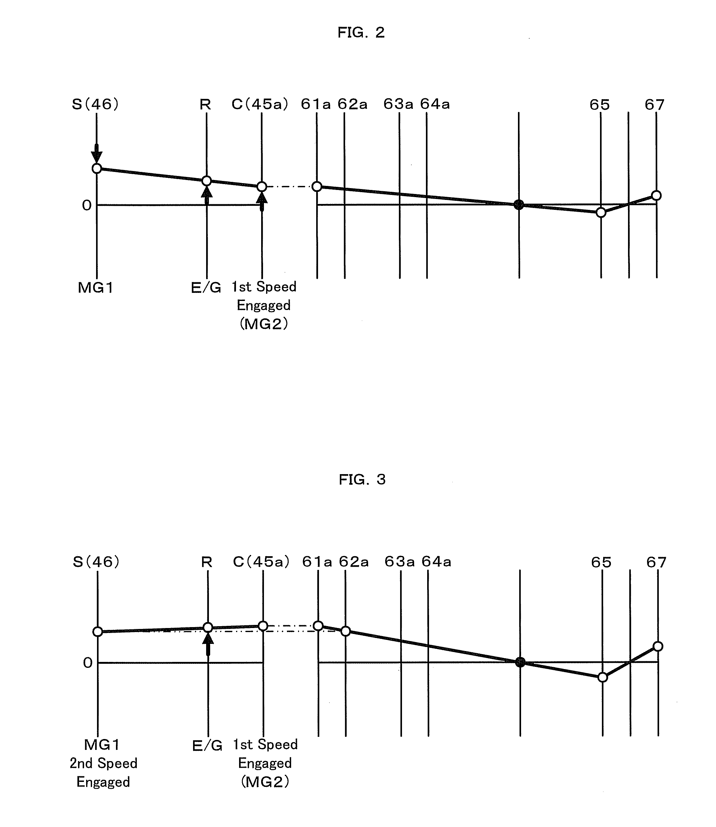
[0010]In one preferable application of the power output apparatus according to the above aspect of the invention, the main motor is one of the first motor and the second motor provided with larger speed ratio with respect to the driveshaft by the speed change-transmission
assembly. In the state of connection of both the two motors with the driveshaft by means of the speed change-transmission assembly to output power to the driveshaft, the main motor is controlled to preferentially output the power, while the auxiliary motor is controlled to output the power for filling the deficiency. Such control ensures stable, smooth, and continuous output of a relatively large torque.
[0011]In another preferable application of the power output apparatus according to the above aspect of the invention, the controller sets a target torque, which is to be output from the main motor, based on the set power demand to be not greater than at least a rated torque of the main motor, while setting a target torque, which is to be output from the auxiliary motor, based on the set power demand and the set target torque of the main motor. In the power output apparatus of this application, the controller may set the target torque, which is to be output from the main motor, to be less than the rated torque of the main motor and not less than a preset minimum output torque, which is smaller than the rated torque. This arrangement ensures adequate settings of a torque to be output by the main motor and a torque to be output by the auxiliary motor.
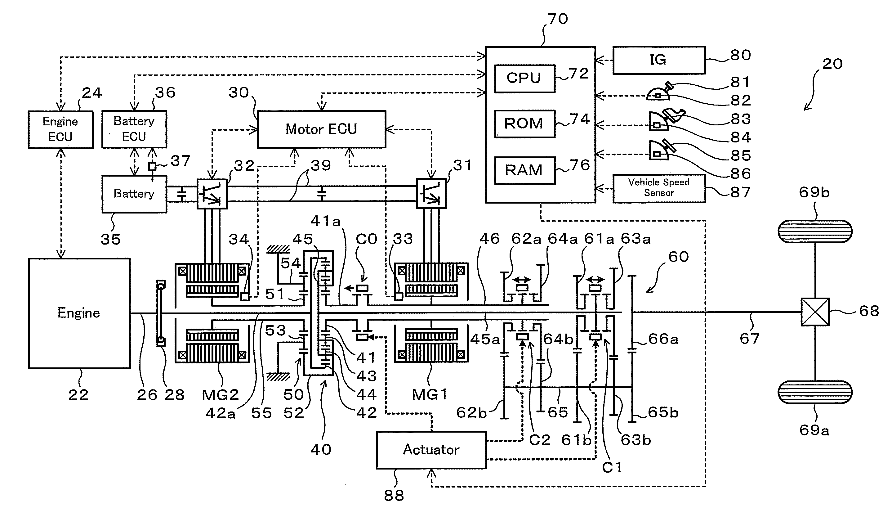
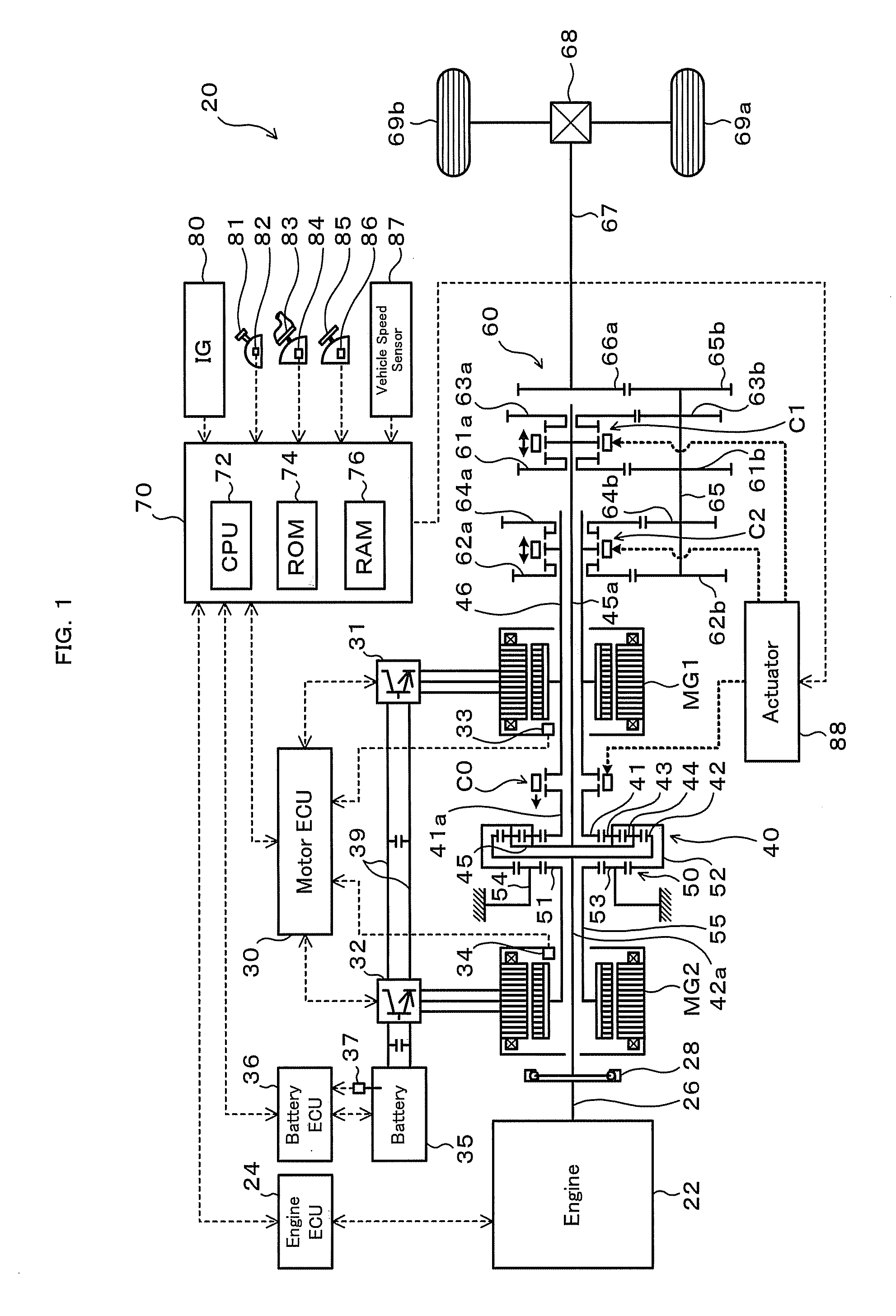
[0012]In one preferable embodiment of the invention, the power output apparatus of the above aspect further has: an
internal combustion engine; a power distribution integration mechanism configured to have a first element connecting with the rotating shaft of the first motor, a second element connecting with the rotating shaft of the second motor, and a third element connecting with an engine shaft of the internal
combustion engine and arranged to allow mutually differential rotations of the three elements; and a connecting-disconnecting device configured to attain driving
source element connection and release of the driving
source element connection. The driving
source element connection may be any one of connection of the first motor with the first element, connection of the second motor with the second element, and connection of the internal
combustion engine with the third element. The driving source element connection may be released by the connecting-disconnecting device and operation of the internal
combustion engine may be stopped when both the first motor and the second motor are connected to the driveshaft by the speed change-transmission assembly. The power output apparatus of this embodiment adequately changes over the driving state between a drive mode with output of the power to the driveshaft accompanied by operation of the internal combustion engine and a drive mode with transmission of the power from at least one of the first motor and the second motor to the driveshaft by means of the speed change-transmission assembly. This arrangement desirably improves the energy efficiency and the
power transmission efficiency of the power output apparatus.
[0014]The motor vehicle according to this aspect of the invention connects both the two motors to the driveshaft by means of the speed change-transmission assembly and thereby ensures continuous output of a relatively large torque. The motor vehicle of this arrangement accordingly has the improved
hill climbing performance and the improved
towing performance in a
motor drive mode with these motors.
[0016]In the state of connection of both the first motor and the second motor with the driveshaft by means of the speed change-transmission assembly to output power to the driveshaft, the control method according to this aspect of the invention controls one of the first motor and the second motor specified as the main motor to preferentially output power, while controlling the other of the first motor and the second motor specified as the auxiliary motor to output power of filling a deficiency of the power demand. Such control ensures continuous output of a relatively large torque, while preventing excessive heat evolution in either of the first motor and the second motor and significant decreases of the respective motor efficiencies. The control method of this aspect also effectively prevents a variation in power output to the driveshaft due to a difference between the responses of the first motor and the second motor to respective power command values, as well as the occurrence of vibration. In the state of connection of both the two motors with the driveshaft by means of the speed change-transmission assembly, this arrangement ensures adequate control of the two motors.

