Shutter clutch

a clutch and clutch technology, applied in the field of clutch systems, can solve the problems of small increase in dimensions, increase in breakpoint torque, and nonlinear production, and achieve the effects of simple design, easy field serviceability, and small number of parts

Active Publication Date: 2010-01-28
AIR MOTION SYST
View PDF9 Cites 3 Cited by
  • Summary
  • Abstract
  • Description
  • Claims
  • Application Information

AI Technical Summary

Benefits of technology

[0010]One feature of one embodiment of the clutch of this invention is that it is ambidextrous, i.e., fitting either shutter. Another feature of an embodiment of the instant clutch is that it will function at a predetermined breakpoint torque whether driven internally by the shutter shaft or manually. The clutch of this invention is further bidirectional in function, exhibiting the same breakpoint torque value regardless of whether torque is applied clockwise or counterclockwise. In use, a combination of the orientation of the UV module, gravity and location of the center of mass of the shutter extrusion may allow the clutch to be slightly easier to override when the shutters are forced toward a closed position. The use of the indexing design of the clutch of this invention and the shutter hard stops which may be built into the UV module assembly enable the instant clutch to automatically reengage to the desired open or closed shutter position when the overload torque condition has been rectified and the shutter drive gear motor energized. This semi-automatic re-engagement feature is advantageous when operating and maintaining a UV module, especially so for quickly and easily installing and / or removing UV lamps and exposing shutter reflectors for cleaning and other maintenance. Regardless of the breakpoint torque value of the clutch of this invention, its external dimensions remain the same.
[0011]The clutch of this invention can be easily adjusted to a desired breakpoint value suitable for any size UV module. Consequently a UV module may include a clutch of this invention with a breakpoint torque, which is specific to the length, hence weight, of the shutters for a module of that size. Consequently, clutch operation will be more reliable and consistent, regardless of the skill and knowledge of the persons assembling and / or servicing the module. Unlike the clutch of the prior art, there is no requirement for adjusting of spring tension, or the like, in order to achieve a clutch with a desired breakpoint torque. Rather a predetermined combination of wave springs, thrust washers, and quantity of detent balls is provided for each size module. In any specific clutch configuration a nominal breakpoint torque required to disengage the clutch is linearly proportional to the number of detent balls used. The shutter shaft flange, accordingly, maybe manufactured to include a specific number of detent holes arranged in a radial array. The number of detent balls used may vary from a quantity of one to virtually any number necessary to achieve the desired breakpoint torque. Additionally, small increases in dimensions such as diameters of detent holes of the clutch plate can produce nonlinear, e.g. exponential, increases in breakpoint torque.
[0022]By using the indexing clutch design of this invention and a special shutter hard stops built into the UV module assembly, the clutch of this invention may automatically reengage itself in the desired opened or closed shutter position once the overload torque condition has been rectified and the motor is energized.
[0023]During normal UV module shutter operation with the instant clutch engaged, there is no relative motion among the clutch components. These clutch components are therefore free of wear while the clutch is engaged.
[0027]Whether or not the instant clutch is in an engaged or disengaged mode, the clutch is designed with features providing a highly desirable multi-axial freedom of motion enabling reliable functionality of the UV shutter module assemblies and the shutter drive train assembly. In a nominal over torque condition, there is very little or no linear displacement of the shutter drive arm, sensor magnet, or shutter end caps, relative to any part of the UV module. If a long term continuous torque overload situation occurs, there is minimal relative motion between clutch components. Accordingly the clutch components wear very little when the clutch is disengaged. The foregoing arrangement assures reliable clutch performance, reliable shutter action, reliable shutter position sensing, and produces no detrimental effect on the shutter shaft-to-shutter end cap seal arrangement. Thus, the clutch design of this invention contributes to minimizing shutter drive train binding, minimizing coolant leakage, and maximizing UV module reliability.
[0029]The clutch of this invention is easily field serviceable, due to its simple design, small number of parts, and ease of assembly and disassembly.

Problems solved by technology

Additionally, small increases in dimensions such as diameters of detent holes of the clutch plate can produce nonlinear, e.g. exponential, increases in breakpoint torque.

Method used


Image

  • Shutter clutch
  • Shutter clutch
  • Shutter clutch

Examples


Embodiment Construction

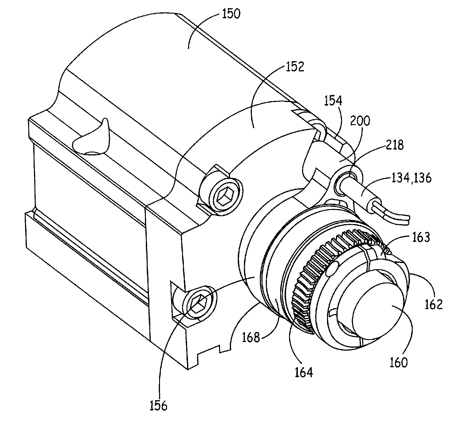
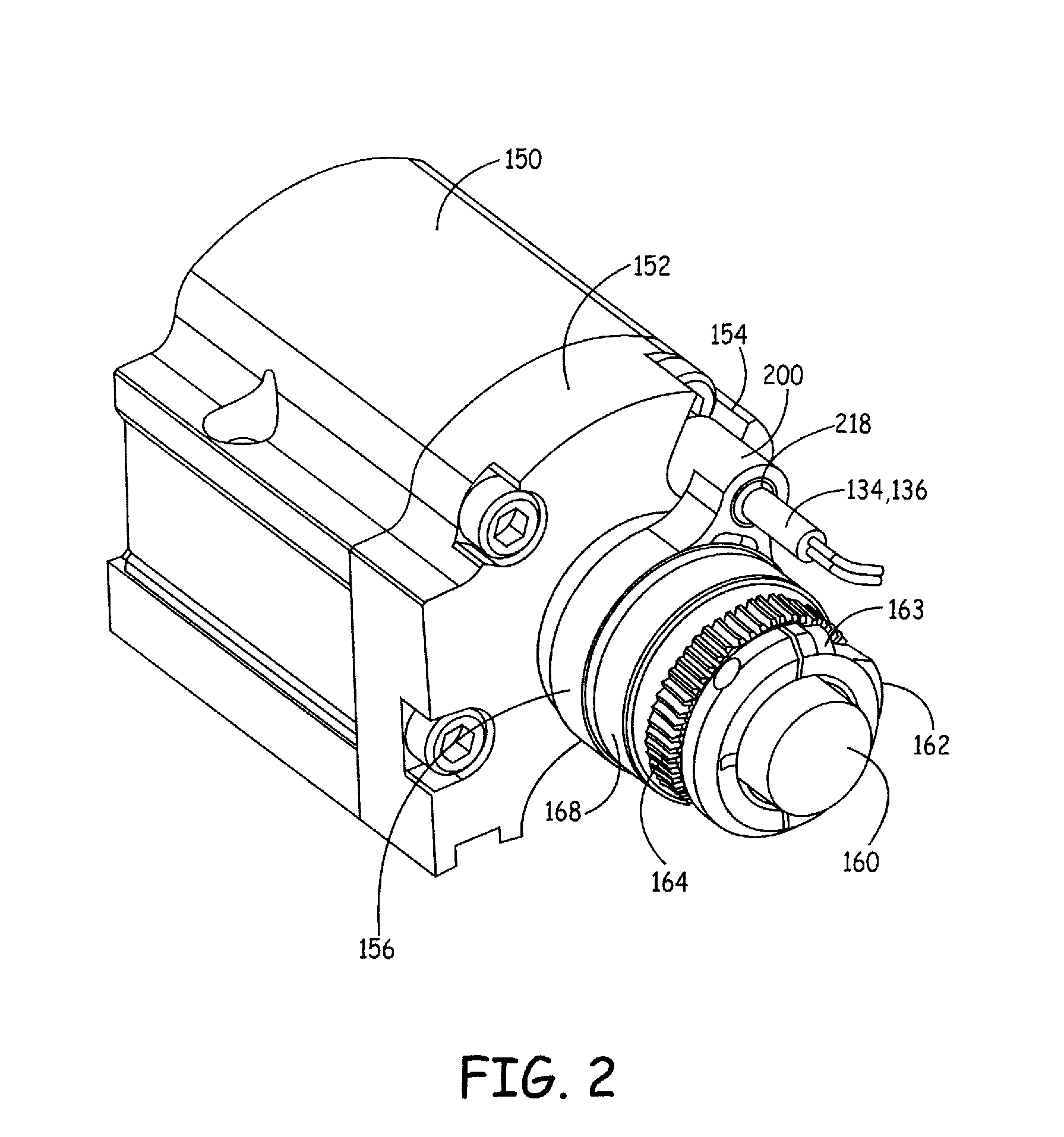
[0043]Each of the features and methods disclosed herein may be utilized separately or in conjunction with other features and methods to provide improved embodiments of this invention and methods for making the same. Representative examples of the teachings of the present invention, which examples utilize many of these additional features and methods in conjunction, will now be described in detail with reference to the drawings. This detailed description is merely intended to teach a person of skill in the art further details for practicing preferred aspects of the present teachings and is not intended to limit the scope of the invention. Therefore, combinations of features and methods disclosed in the following detailed description may not be necessary to practice the invention in the broadest sense, and are instead taught merely to particularly describe representative and preferred embodiments of the invention The clutch of this invention is advantageously present in a UV module 10...


PUM

PropertyMeasurementUnit
temperaturesaaaaaaaaaa
diameteraaaaaaaaaa
depthaaaaaaaaaa

Abstract

A clutch assembly for a UV module shutter, comprises a shutter shaft, a shutter drive arm, a clutch plate, at least one ball, a clutch thrust washer, and a spring assembly. The shutter shaft has a flange, the flange having a plurality of radially positioned flange detents. The shutter drive arm includes a drive pin, a drive arm cavity, and a receiver slot opening into the drive arm cavity, the drive pin disposable in a drive slot of a shutter end cap. The clutch plate may be disposed in the clutch plate cavity, may have a tab disposed in the receiver slot and a plurality of clutch plate detents. Each of the ball(s) may extend from one of the flange detents and may be partially disposable in one of the clutch plate detents. The spring assembly may exert a bias against the clutch plate and the thrust washer. The shutter shaft may extend through the shutter drive arm, the clutch plate, and the clutch thrust washer.

Description

BACKGROUND OF THE INVENTION [0001]1. Field of the Invention[0002]This invention relates to printing presses and, in particular, this invention relates to clutch systems for UV modules used in printing presses.[0003]2. Background of the Invention[0004]Ultraviolet-sensitive ink is used widely in the printing industry. One reason for its use is that ultraviolet-sensitive ink can be quickly cured by being irradiated with ultraviolet light. Such irradiation is accomplished by directing a light beam, containing high proportions of ultraviolet light, at the printed substrate.[0005]Lamps used to generate light for this purpose also generate considerable amounts of other energy in the form of heat. This heat is usually of little consequence when a printing press is operating, because the light and heat are directed toward the substrate which is in motion during the printing process. However, if the heat and light generated by the lamp is directed at a nonmoving substrate for a sufficient amo...

Claims


Application Information

Patent Timeline
Patent Type & Authority Applications(United States)
IPC IPC(8): F16D7/06B23P11/00
CPCB41F23/0409Y10T29/49826F16D7/08
Inventor CLAEYS, MICHAEL L.
Owner AIR MOTION SYST
Why Eureka
Try Eureka