Liquid crystal panel and liquid crystal display

a liquid crystal display and panel technology, applied in the field of liquid crystal panels and liquid crystal displays, can solve the problems of insufficient improvement and achieve the effect of excellent color display characteristics

Active Publication Date: 2010-01-28
NITTO DENKO CORP
View PDF6 Cites 7 Cited by
  • Summary
  • Abstract
  • Description
  • Claims
  • Application Information

AI Technical Summary

Benefits of technology

[0013]The inventors have made eager research of causes for color shift. As a result, the inventors have paid attention to a relationship between the wavelength dispersion of the retardation of a liquid crystal cell and the wavelength dispersion of the retardation of an optical compensation layer. Thus, the inventors have found out that the color shift of a liquid crystal panel can be prevented by using an optical compensation layer exhibiting a reverse wavelength dispersive property and an optical compensation layer exhibiting a flat wavelength dispersive property in a liquid crystal cell exhibiting a reverse wavelength dispersive property.
[0017]In the liquid crystal panel of the present invention, color shift is hardly caused even when the panel is viewed from all azimuth angle directions and polar angle directions. Thus, the panel is excellent in color display characteristics.
[0029]About the liquid crystal display comprising any one of the above-mentioned liquid crystal panels, a color display perceived when the display is viewed from an oblique direction is substantially equivalent to that perceived when the display is viewed from the front direction. Thus, the liquid crystal display is excellent in color display characteristics.

Problems solved by technology

However, according to the liquid crystal panels, a sufficient improvement is not made against a problem of color shift (color change) caused when the panels are each viewed from an oblique direction thereof.

Method used


Image

  • Liquid crystal panel and liquid crystal display
  • Liquid crystal panel and liquid crystal display
  • Liquid crystal panel and liquid crystal display

Examples


example 1

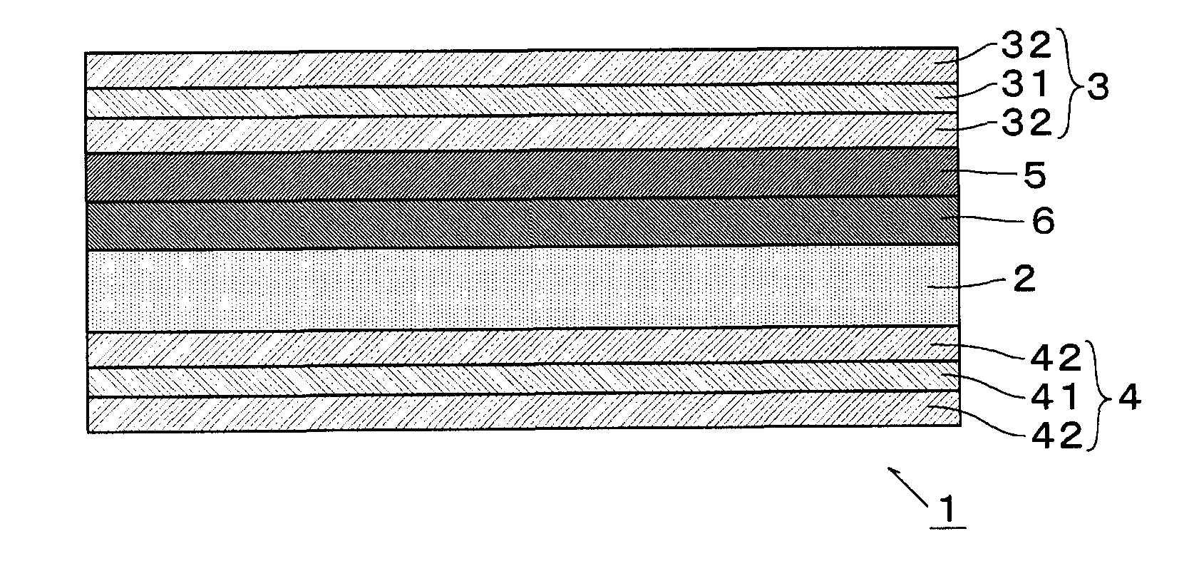
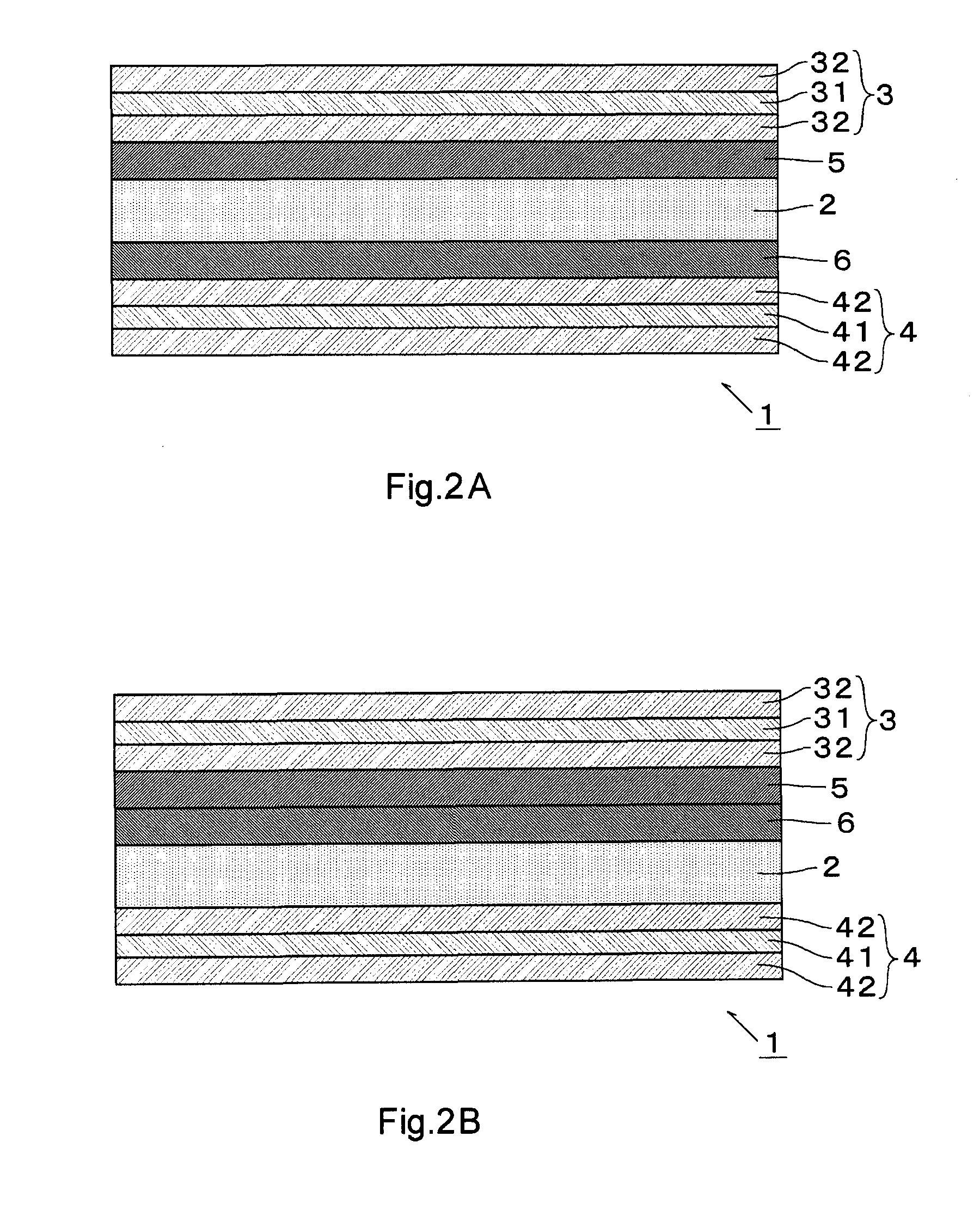
[0138]The optical compensation layer (1) was adhered onto the viewing surface side of the liquid crystal cell through an acrylic pressure-sensitive adhesive (thickness: 5 μm), and then one of the polarizing plates (a) was adhered onto one of the surfaces of the optical compensation layer (1) (the uncovered surface opposite to the surface bonded to the liquid crystal cell). Two of the optical compensation layers (2) were adhered onto the surface opposite to the viewing side surface of the liquid crystal cell through the same pressure-sensitive adhesive as described above. Another plate of the polarizing plates (a) was adhered onto the uncovered surface of the lower layer of the optical compensation layers (2) through the same pressure-sensitive adhesive.

[0139]About the resultant liquid crystal panel, the XY chromaticity was measured. Results as shown in FIGS. 3 and 4 were obtained. As is evident from the results, the chromaticity of the liquid crystal panel of Example 1 was a value c...


PUM

PropertyMeasurementUnit
angleaaaaaaaaaa
angleaaaaaaaaaa
angleaaaaaaaaaa

Abstract

The liquid crystal panel 1 of the present invention comprises a liquid crystal cell 2, a first polarizer 31 disposed on one surface side of the liquid crystal cell 2, a second polarizer 41 disposed on the other surface side of the liquid crystal cell 2, and first optical compensation layer 5 and second optical compensation layer 6 disposed between the first polarizer 31 and second polarizer 41, and the liquid crystal cell 2 satisfies a relationship of 0.8<Re[450] / Re[550]<1, the first optical compensation layer 5 satisfies relationships of the Nz coefficient is from 0.8 to 1.4 and 0.8<Re[450] / Re[550]<1, and the second optical compensation layer 6 satisfies relationships of nx=ny>nz and 0.98<Re[450] / Re[550]<1.04.The liquid crystal panel of the present invention is hardly generated color shift when the panel is viewed from all azimuth angle directions and polar angle directions, so that the liquid crystal panel is excellent in color display characteristics.

Description

TECHNICAL FIELD[0001]The present invention relates to a liquid crystal panel, and a liquid crystal display.BACKGROUND ART[0002]As liquid crystal displays, for example, in a VA mode, there have been hitherto known a transmission type liquid crystal display, a reflection type liquid crystal display, and a semi-transmission type liquid crystal display (Patent Documents 1 and 2).[0003]A liquid crystal cell of the liquid crystal displays has two liquid crystal cell substrates, a spacer interposed between the two liquid crystal cell substrates, and a liquid crystal material injected into a gap between the two liquid crystal cell substrates (the layer made of the liquid crystal material is called a liquid crystal layer). The thickness (cell gap) of the liquid crystal layer is kept constant by the spacer.[0004]This liquid crystal layer itself has birefringence, and generates a retardation. In order to improve a deterioration in the viewing angle resulting from the retardation, an optical co...

Claims


Application Information

Patent Timeline
Patent Type & Authority Applications(United States)
IPC IPC(8): G02F1/13363
CPCG02B5/3016G02F2001/133637G02F1/133634G02F1/133637
Inventor NAGASE, JUNICHITAKEDA, KENTAROU
Owner NITTO DENKO CORP
Why Eureka
Try Eureka