Mobile communication system, its control device, handover control method, and mobile terminal

a mobile terminal and control device technology, applied in wireless communication services, wireless commuication services, electrical equipment, etc., can solve the problems of increasing the cost of mobile terminals, increasing user burden, suitably coping, etc., and achieves the effect of reducing the cost of terminals and speeding up the handover

Inactive Publication Date: 2010-01-28
KK TOSHIBA
View PDF10 Cites 20 Cited by
  • Summary
  • Abstract
  • Description
  • Claims
  • Application Information

AI Technical Summary

Benefits of technology

[0018]That is, since the system side may predict a base station for a handover destination (a base station of the next connection destination), the system can perform handovers on the network side, instead of by the mobile terminal itself. Thereby, utilizing sufficient resources enables speeding up of the handovers. Further, since parts relating to the processing performed by the mobile terminal can be omitted, the cost of terminals can be reduced.

Problems solved by technology

Since handovers occur frequently in the micro cell system, the system may not be able to suitably cope with high-speed movements of mobile terminals, thus posing a problem.
For instance, an enhancement of high-speed movement performance by using such technique in this reference increases mobile terminal costs, and increases the burden on users.
In this technique, since it is necessary to specify ranges of communication areas (zones) in advance for implementation of the technique, this technique cannot be applied to a system in which station installation design is not performed.

Method used


Image

  • Mobile communication system, its control device, handover control method, and mobile terminal
  • Mobile communication system, its control device, handover control method, and mobile terminal
  • Mobile communication system, its control device, handover control method, and mobile terminal

Examples


first embodiment

[0065]FIG. 8 shows a schematic view illustrating an example of an actual handover. In FIG. 8, it is assumed that the base stations CS1-CS4 form wireless communication areas (wireless zones) A301-A304, respectively, and the mobile terminal PS moves sequentially in the communication areas from the area A301 to the area A304. When reaching near a boundary between the area A301 and the area A302, the mobile terminal PS performs a handover to the base station CS2. The control unit 4 stores the time when the handover is performed. The time may be Japan Standard Time, or may be a time elapsed from a start of call communication. Similarly, the control device 4 also stores the time when the mobile terminal PS performs its handover to the base station CS3 and the time when the mobile terminal PS performs its handover to the base station CS4.

[0066]The control device 4 stores a period in which the mobile terminal PS communicates with the base station CS1, a period in which the mobile terminal P...

second embodiment

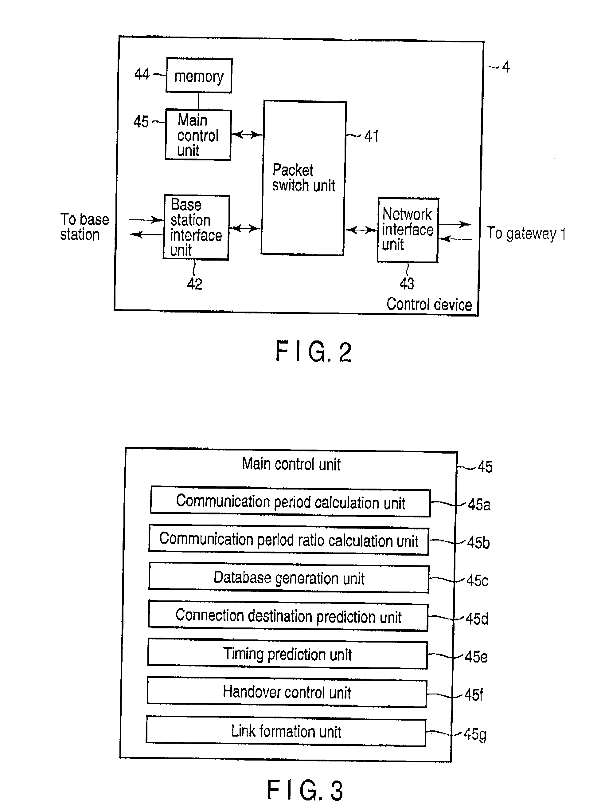
[0084]FIG. 11 shows a block diagram illustrating functions provided for the main control unit 45 (control device 4) of the second embodiment of the invention. FIG. 12 shows a view illustrating an example of information to be stored in the memory 44 shown in FIG. 3 of the second embodiment. In FIG. 11, the same components as those in FIG. 3 are designated by the identical symbols, and in FIG. 12, the same components as those in FIG. 4 are designated by the identical symbols. Herein, solely different components will be described. In the second embodiment, the main control unit 45 has a remaining resource management unit 45h in addition to the configuration shown in FIG. 3. The resource management unit 45h has a function of recognizing the remaining resources amount varying every moment in real time. The resources include the remaining of the communication channels or the remaining number of links capable of being formed in the communication resources. The latest recognized remaining r...


PUM


Abstract

According to one embodiment, a mobile communication system includes base stations each forming a wireless zone for wirelessly accommodating mobile terminals, and a control device accommodating the base stations. The control device includes a construction module, a prediction module and an instruction module. The construction module constructs a database regarding a history of handovers by the mobile terminals. The prediction module predicts a base station of the next connection destination of a mobile terminal being in communication and timing of a handover to the base station of the next connection destination on the basis of the database. The instruction module instructs the handover to the predicted base station to the mobile terminal being in communication before the timing comes.

Description

CROSS-REFERENCE TO RELATED APPLICATIONS[0001]This application is based upon and claims the benefit of priority from prior Japanese Patent Application No, 2008-193923, filed Jul. 28, 2008, the entire contents of which are incorporated herein by reference.BACKGROUND OF THE INVENTION[0002]1. Field of the Invention[0003]One embodiment of the present invention relates to an improvement of a mobile communication system that forms areas, for example, in a micro cell system.[0004]2. Description of the Related Art[0005]Systems in which a mobile communication system forms areas are classified roughly into macro cell systems and micro cell systems. A representative of the former is a so-called cellular phone system, and the radius of each wireless area reaches several kilometers. A Personal Handy-phone System (PHS) adopts the latter system, and the radius of each wireless area is very small and is on the order of no more than several hundred meters,[0006]For the micro cell system, the number o...

Claims


Application Information

Patent Timeline
Patent Type & Authority Applications(United States)
IPC IPC(8): H04W36/00
CPCH04W36/245H04W36/008375
Inventor YAMAMOTO, KEIJINEGISHI, KAZUYA
Owner KK TOSHIBA
Why Eureka
Try Eureka