Apparatus, imaging device and method for counting x-ray photons

an imaging device and counting method technology, applied in the direction of material analysis using wave/particle radiation, instruments, nuclear engineering, etc., can solve the problems of significant reduction of the energy resolution of the imaging device, affecting the counting performance, and only partially processing events/photons, etc., to achieve the effect of improving the counting performan

Active Publication Date: 2010-01-28
KONINKLIJKE PHILIPS ELECTRONICS NV
View PDF8 Cites 32 Cited by
  • Summary
  • Abstract
  • Description
  • Claims
  • Application Information

AI Technical Summary

Benefits of technology

[0010]It is an object of the present invention to provide an apparatus for counting X-ray photons, in particular photons in a computer tomograph, having an improved counting performance. It is a further object of the present invention to provide a c

Problems solved by technology

Such pile-up events can lead to incorrect results and can significantly reduce the energy resolution of the imaging device.
How

Method used


Image

  • Apparatus, imaging device and method for counting x-ray photons
  • Apparatus, imaging device and method for counting x-ray photons
  • Apparatus, imaging device and method for counting x-ray photons

Examples


first embodiment

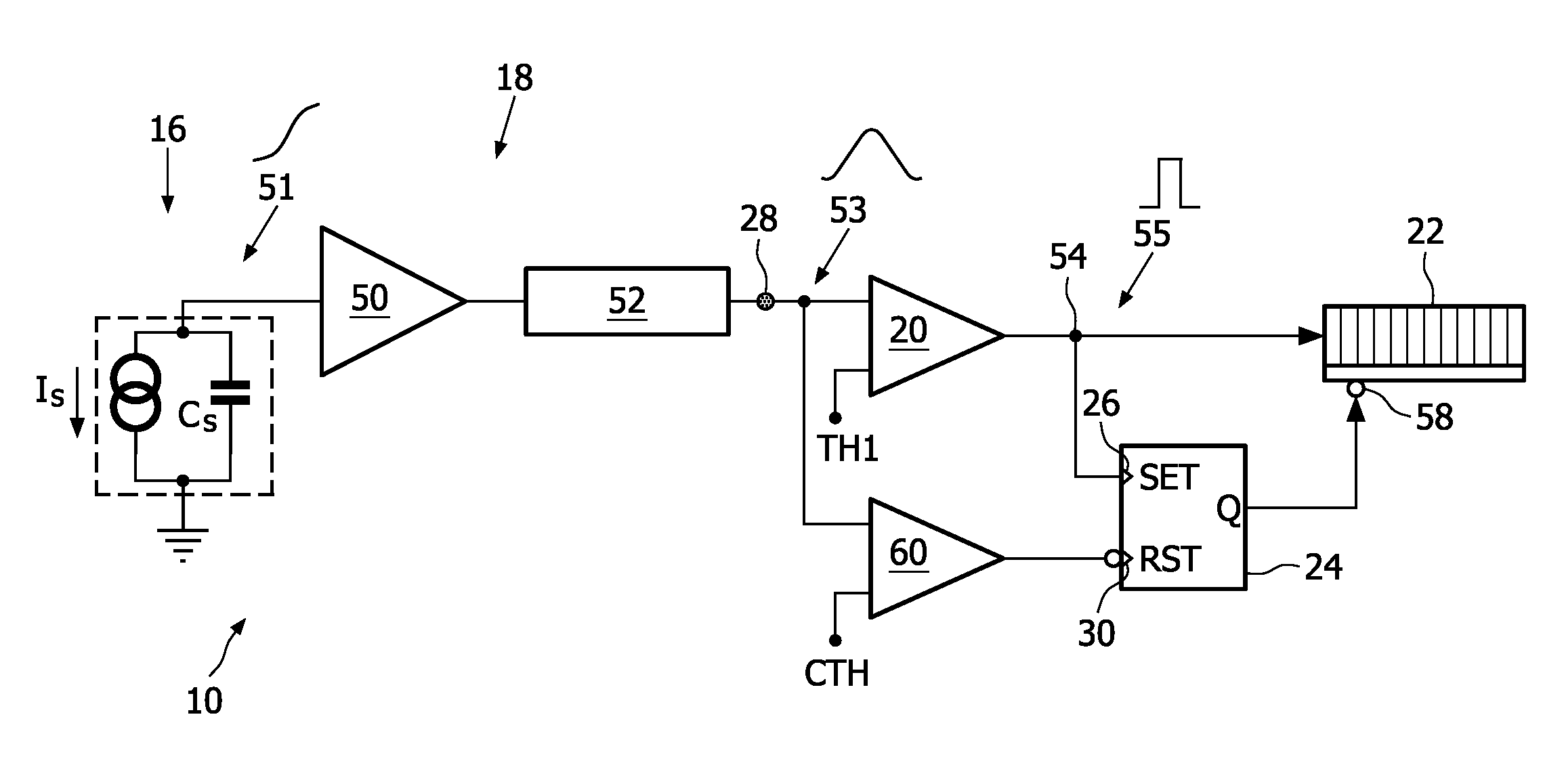
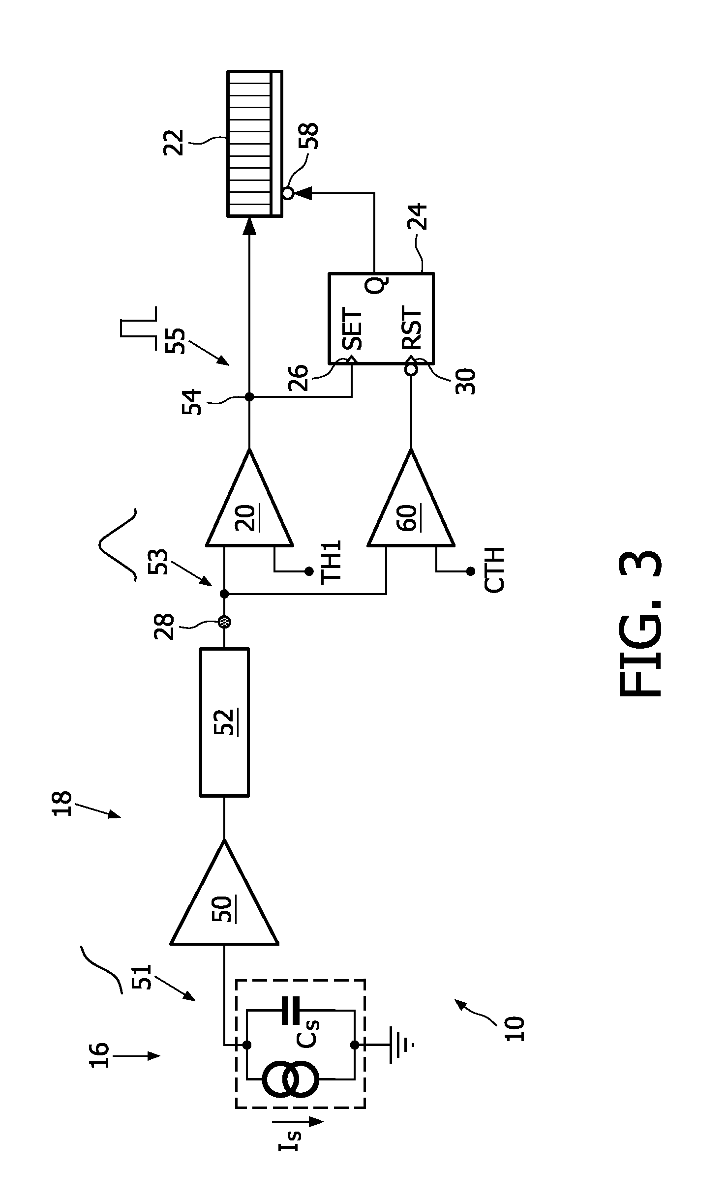
[0077]FIG. 3 shows the apparatus 10 according to the present invention.

[0078]The sensor 16 is symbolized as a current source providing a current Is in parallel to a capacitance Cs The processing element 18 is implemented by a preamplifier 50, that receives a charge pulse 51 from the sensor 16, followed by a shaper 52. While the preamplifier 50 essentially acts as an integrator for the charge pulse 51 coming from the sensor 16, the shaper 52 provides an electrical pulse 53 having a rising flank and a falling flank. The output 28 of the processing element 18 corresponds in this case to an output of the shaper 52.

[0079]The first discriminator 20 is connected to the output 28 of a processing element 18, and an output 54 of the first discriminator 20 is connected to an input of the first counter 22.

[0080]The first gating element 24 is embodied as a flip-flop, having a set-input as the activation input 26 and a reset-input as the deactivation input 30.

[0081]The first gating element 24 fur...

second embodiment

[0092]FIG. 5 shows an apparatus 10 according to the present invention which employs multiple thresholds for discriminating the energy levels of the incoming photons 12, 14.

[0093]The shown apparatus 10 bases on the apparatus 10 according to FIG. 3, so that only the differences will be described in the following.

[0094]The apparatus 10 comprises a second discriminator 70 which is connected in parallel to the first discriminator 20. The second discriminator 70 is connected to a second counter 72 which is adapted to count events. Further, the second discriminator 70 is adapted to compare the electrical pulse 53 against a second threshold TH2 and to output an event if the second threshold TH2 is exceeded.

[0095]As indicated by a third discriminator 74 having a third threshold TH3, this concept can be extended to a plurality of discriminators and a plurality of counters. However, for clarity reasons, only the necessary basics regarding the introduction of the second discriminator 70 are exp...

third embodiment

[0099]FIG. 6 shows the apparatus 10 according to the present invention. It is similar to the embodiment shown in FIG. 5, however the concept of gating the second counter 72 is changed. While this difference is explained in more detail, reference is made to FIG. 5 for all other details.

[0100]As shown, a disable-input 58′ of the second counter 72 is connected to the output Q of the first gating element 24 via a delay element 90. This means, that a signal coming from the first gating element 24 disabling the first counter 22 is transmitted to the second counter 72 delayed by a certain time duration specified by the delay element 90.

[0101]While the delay element 90 is not mandatory, it is preferably used in order to avoid a situation, where the second counter 72 is disabled, due to the electrical pulse 53 exceeding the first threshold TH1, before the electrical pulse 53 has risen above the threshold TH2, thereby the second counter 72 missing a count.


PUM


Abstract

The present invention relates to an apparatus (10) for counting X-ray photons (12, 14). The apparatus (10) comprises a sensor (16) adapted to convert a photon (12, 14) into a charge pulse, a processing element (18) adapted to convert the charge pulse (51) into an electrical pulse (53) and a first discriminator (20) adapted to compare the electrical pulse (53) against a first threshold (TH1) and to output an event (55) if the first threshold (TH1) is exceeded. A first counter (22) counts these events (55), unless counting is inhibited by a first gating element (24). The first gating element (24) is activated when the first discriminator (20) outputs the event (55), and it is deactivated, when the processing of a photon (12, 14) is found to be complete or about to be completed by a measurement or by the knowledge about the time that it takes to process a photon (12, 14) in the processing element (18). By activating and deactivating the first counter (22) pile-up events, i.e. pile-up of multiple electrical pulses (53), can be addressed. The invention also relates to a corresponding imaging device and a corresponding method.

Description

FIELD OF THE INVENTION[0001]The present invention relates to an apparatus, an imaging device and a method for counting X-ray photons, in particular photons in a computer tomograph.BACKGROUND OF THE INVENTION[0002]Computer tomography (CT, also called computed tomography) has evolved into a commonly used means, when it comes to generating a three-dimensional image of the internals of an object. The three-dimensional image is created based on a large number of two-dimensional X-ray images taken around a single axis of rotation. While CT is most commonly used for medical diagnosis of the human body, it has also been found applicable for non-destructive materials testing. Detailed information regarding the basics and the application of CT, can be found in the book “Computed Tomography” by Willi A. Kalender, ISBN 3-89578-216-5.[0003]One of the key innovative aspects in future CT and X-ray imaging is the energy-resolved counting of the photons which are let through or transmitted by the ob...

Claims


Application Information

Patent Timeline
IPC IPC(8): G21K1/12
CPCG01T1/2928G01T1/17
Inventor STEADMAN BOOKER, ROGERBAEUMER, CHRISTIANHERRMANN, CHRISTOPHZEITLER, GUENTER
Owner KONINKLIJKE PHILIPS ELECTRONICS NV
Why Eureka
Try Eureka