X-ray tube

a technology of x-ray tubes and x-ray electrodes, which is applied in the direction of x-ray tube electrodes, cathode ray concentrating/focusing/directing, diagnostics, etc., can solve the problems of unable to allow single or half rotation cardiac ct scanning, difficult problems, and temporal resolution

Active Publication Date: 2010-01-28
ARINETA
View PDF32 Cites 8 Cited by
  • Summary
  • Abstract
  • Description
  • Claims
  • Application Information

AI Technical Summary

Benefits of technology

[0033]In an exemplary embodiment of the invention, one or more closed gates prevent transmission of an electron beam to one or more ano

Problems solved by technology

When moving organs are involved, however, especially the beating heart, the temporal resolution, i.e. ‘freezing’ the organ, is problematic.
One area of current interest is CT scanning of the heart, referred to as “cardiac CT.” This presents especially difficult problems since the length of image that is required is of the order of 120 mm.
Thus, this system does not allow for single or half rotation cardiac CT scanning.
These systems are inherently inefficient in utilization of the X radiation since most radiation is absorbed by the septa while still requiring high power, generating high heat load, to energize the sources.
Unfortunately, with these types of solutions the reconstructed images have artifacts that worsen with the distance from the mid plane (the source trajectory plane) due to “data incompleteness”.
Similar problems occur wi

Method used


Image

  • X-ray tube
  • X-ray tube
  • X-ray tube

Examples


Embodiment Construction

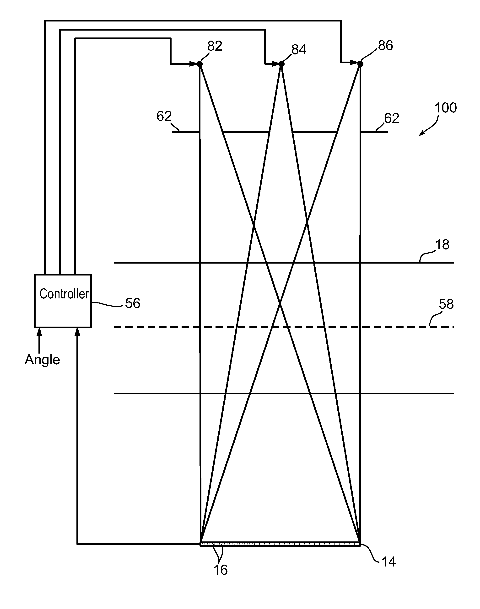
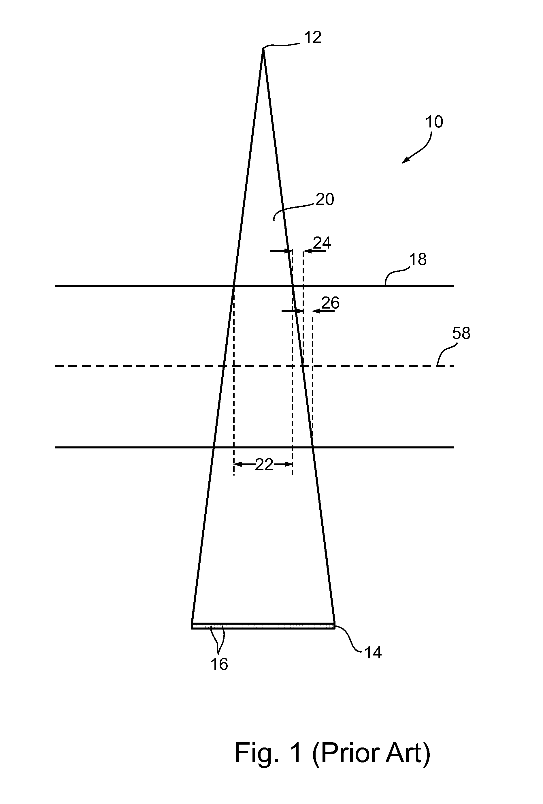
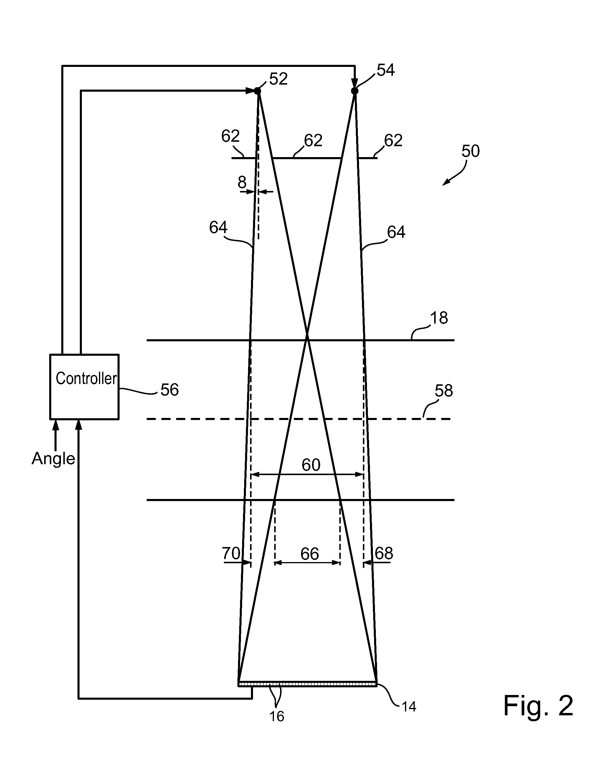
[0089]FIG. 2 is a view similar to that of FIG. 1, showing a system 50 utilizing two sources 52 and 54 to apply radiation to patient while providing attenuation data in a half rotation of the sources or optionally a larger rotation angle, in accordance with an exemplary embodiment of the invention. FIG. 2 is to scale. For simplicity the support structures holding the sources 52 and 54 as well as other parts of system 50 are not shown.

[0090]As shown in FIG. 2, the beams both illuminate the entire axial extent of detector 14, when they are energized. A controller 56 controls the rotation of the sources and detector array 14 about an axis 58 and alternately energizes sources 52 and 54 and acquires data from the detectors that form a part of detector array 14. Data from the detectors, together with the rotation angle at which the data was acquired and the source corresponding to the data is stored and used to reconstruct a CT image of a region 60.

[0091]Collimator 62 limits the extent of ...


PUM


Abstract

An X-ray tube system comprising:
    • at least one filament adapted to produce two electron beams when electrified;
    • at least two anodes spaced from each other along a first direction that each comprises a face that receives an electron beams from the at least one filament at a focal point and produces x-ray cone beams responsive thereto, the x-ray beams being directed in a same direction perpendicular to the first direction;
    • a collimator that collimates the cone beams such that the beams are asymmetric, with the side of each beam distal from the other beam having a smaller beam angle than the side proximal to the other beam.

Description

RELATED APPLICATIONS[0001]This application is a continuation-in-part (CIP) of PCT Patent Application No. PCT / IL2007 / 000461 filed on Apr. 10, 2007, which designated the US. This application is also related to co-pending U.S. patent application Ser. No. 12 / 307,374 filed on Jan. 5, 2009, which is a National Phase of PCT Patent Application No. PCT / IL2007 / 000462 entitled “Cone-Beam CT” and which was filed on Apr. 10, 2007, the same filing date as PCT / IL2007 / 000461. The disclosures of both the above PCT applications are fully incorporated herein by reference.FIELD OF THE INVENTION[0002]The present invention relates to X-ray tubes, methods of use thereof and methods of manufacture thereof.BACKGROUND OF THE INVENTION[0003]The use of X-ray beams in medical imaging is well established. X-Ray projection imaging is used to obtain static or fluoroscopic images. Computerized tomography (CT) scanning uses a plurality of X-ray images to assemble a 3D reconstruction of an organ or a portion of a sub...

Claims


Application Information

Patent Timeline
IPC IPC(8): H01J35/08
CPCA61B6/032A61B6/4014A61B6/4028A61B6/4085A61B6/541A61B6/4291H01J35/14H01J35/24H01J2235/068H01J2235/086A61B6/4021H01J35/04H01J35/147H01J35/153
Inventor DAFNI, EHUD
Owner ARINETA
Why Eureka
Try Eureka