
Method for forming a coupling unit on a long composite fibre section

a technology of composite fiber and coupling unit, which is applied in the direction of textile cables, ropes and cables for vehicles/pulleys, instruments, etc., can solve the problems of high complexity of the method, lack of adequate adhesion area, and high complexity of the manufacturing method, so as to achieve favorable force flow direction

Inactive Publication Date: 2010-01-28
FAIGLE KUNSTE
View PDF1 Cites 1 Cited by
  • Summary
  • Abstract
  • Description
  • Claims
  • Application Information

AI Technical Summary

Benefits of technology

[0014]The invention addresses the problem of providing a method of the above described type which is simple by implementation, by which a secure and reliable anchorage of an elongated composite fiber component on a force application element can be attained, or to provide a secure and reliable such anchorage.
[0022]In an anchorage established through a method according to the invention, the fibers of the composite fiber component can in advantageous manner be maintained, and specifically in a favorable force flow direction. The press force exerted in the formation of the anchorage acts advantageously transversely to the longitudinal direction of the composite fiber component onto its shell surface.

Problems solved by technology

However, one problem consists in applying tension and pressure forces into bar-form composite fiber components such that they are appropriate to the material and force flow involved.
Such a fabrication of continuous loops of composite fiber material, however, involves high complexity, inter alia for each tension bar extent a tool of suitable length is required.
For such adhesions and grouted anchorages, however, an adequate adhesion area must be available which is lacking in some application cases.
Of disadvantage in force-closure connections are the uncertainties due to possibly changing frictional conditions and prestress and possible vibrational or oscillatory friction wear.
A disadvantage is inter alia the complexity of the method.
Through the very strong deformation of the composite fiber material in the region of the connection section, uncertainties with respect to the static and dynamic properties of the anchored composite fiber component can also result in this region and this method is not suitable for all types of composite fiber components.

Method used


Image

  • Method for forming a coupling unit on a long composite fibre section
  • Method for forming a coupling unit on a long composite fibre section
  • Method for forming a coupling unit on a long composite fibre section

Examples


Embodiment Construction

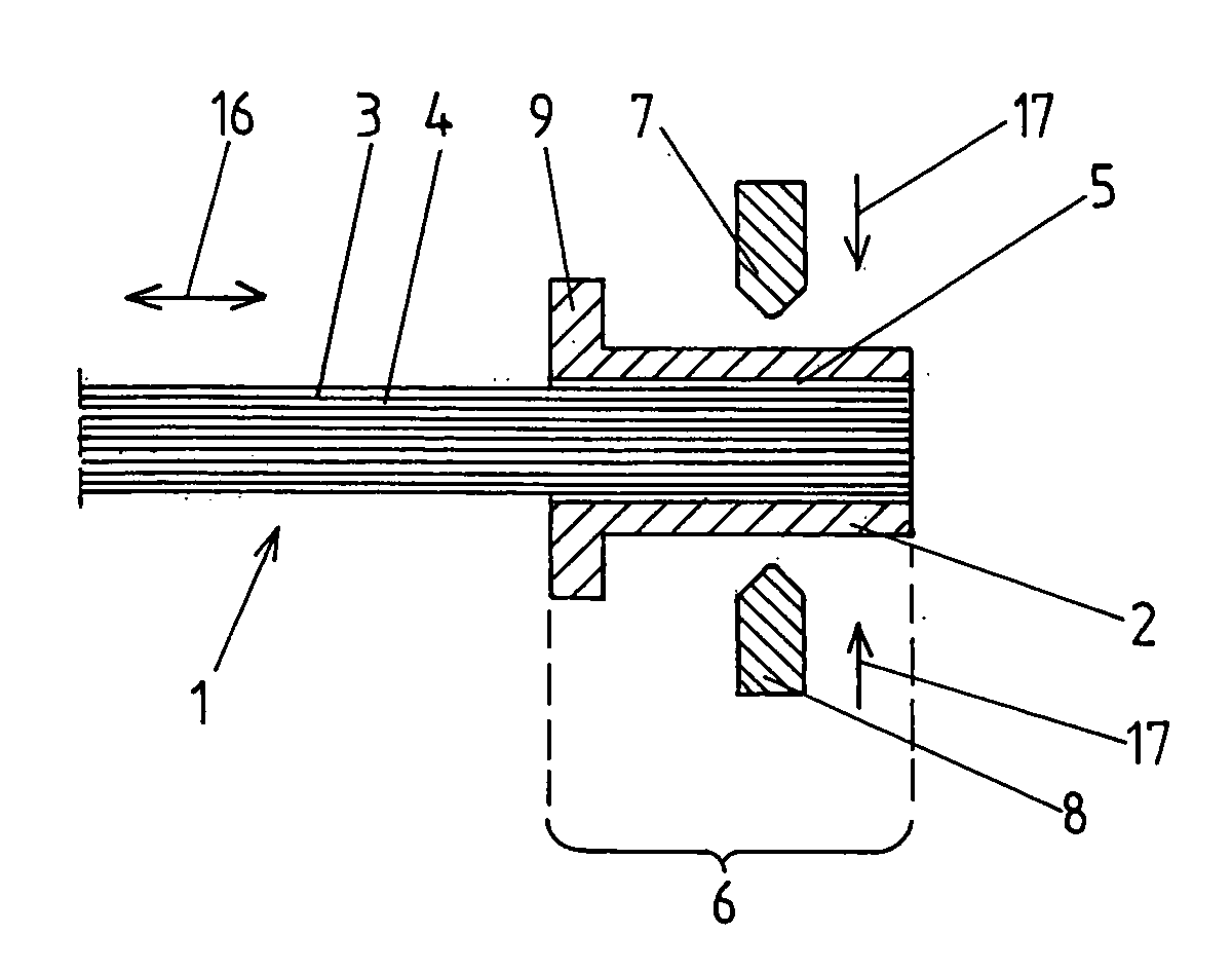
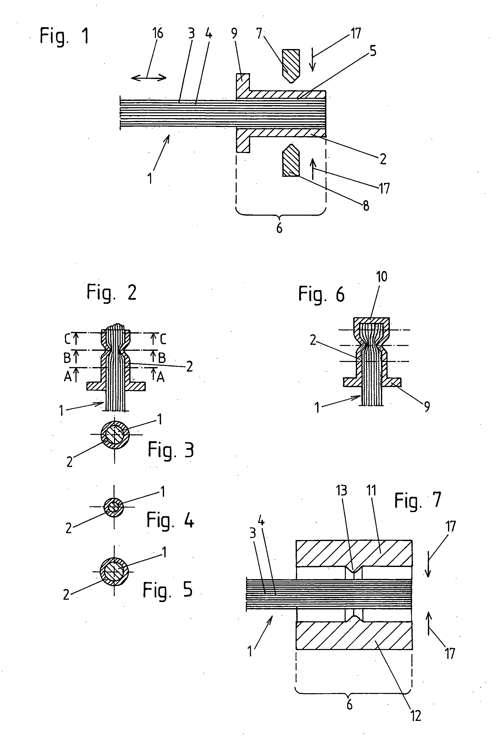
[0034]A first embodiment of the invention will be explained in the following in conjunction with FIG. 1 to 5. Through a method according to the invention an elongated or bar-form composite fiber component 1 is to be anchored on a force application element 2 such that a longitudinal force can be transmitted, acting at least into one of the longitudinal directions of the composite fiber component 1, which directions are indicated in FIG. 1 by the double arrow 16.

[0035]The composite fiber component 1, which is formed in particular as a tension or pressure bar, can have various cross sectional geometries. The cross sectional area and geometry is constant before carrying out the method according to the invention, for example over the entire length of the composite fiber component. In the embodiment according to FIG. 1 to 5 the composite fiber component, before the method according to the invention has been carried out, has at least over a connection section 6, a constant circular cross s...


PUM

PropertyMeasurementUnit
diameteraaaaaaaaaa
diameteraaaaaaaaaa
lengthaaaaaaaaaa

Abstract

In a method for the formation of an anchorage transmitting a longitudinal force, of an elongated composite fiber component, in particular in the form of a tension or pressure bar, which includes a thermoplastic matrix material and fibers embedded therein, on a force application element, which includes a cavity that accepts the composite fiber component over a connection section of its longitudinal extent, between the composite fiber component and the force application element a form-locking connection, acting in the longitudinal direction of the composite fiber component, is formed. For the formation of the form-locking connection the geometry of the composite fiber component, while its temperature is above the glass transition temperature of the matrix material of the composite fiber component in the connection section, is changed through a press force acting onto the external surface of the composite fiber component such that the cross sectional area of the connection section over its longitudinal extent is changed in terms of its areal enclosure. The diameter of the composite fiber component, with respect to at least one certain direction located at right angles to the longitudinal direction of the composite fiber component, is changed over the longitudinal extent of the connection section.

Description

BACKGROUND OF THE INVENTION [0001]a) Field of the Invention[0002]The invention relates to a method for the formation of an anchorage transmitting a longitudinal force, of an elongated composite fiber component, in particular in the form of a tension or pressure bar, which component comprises a thermoplastic matrix material and fibers embedded therein, on a force application element including a cavity, which cavity accepts the composite fiber component over a connection section of its longitudinal extent, wherein between the composite fiber component and the force application element a form-locking connection is formed acting in the longitudinal direction of the composite fiber component. The invention furthermore relates to an anchorage for the transmission of a longitudinal force between an elongated composite fiber component and a force application element.[0003]b) Description of Related Prior Art[0004]Due to the problematic force application into elongated composite fiber compone...

Claims


Application Information

Patent Timeline
Patent Type & Authority Applications(United States)
IPC IPC(8): G02B6/00
CPCC08J5/04G02B6/4439F16G11/02
Inventor DECKER, THOMAS
Owner FAIGLE KUNSTE
Learn More