MRI compatible programmable valve pump

Active Publication Date: 2010-01-28
FLO(ABC) LLC
View PDF5 Cites 18 Cited by
  • Summary
  • Abstract
  • Description
  • Claims
  • Application Information

AI Technical Summary

Benefits of technology

[0014]The problems of the prior art have been overcome by the present invention through the use of a non-magnetic valve/accumulator metering assembly. The solenoids of the prior art, which are susceptible to magnetic fields, are replaced by Shape Memory Alloy (SMA) wires and associated control electro

Problems solved by technology

However, when a patient with such a device enters an MRI (magnetic resonant imaging) environment, the presence of large magnetic fields

Method used


Image

  • MRI compatible programmable valve pump
  • MRI compatible programmable valve pump
  • MRI compatible programmable valve pump

Examples


Example

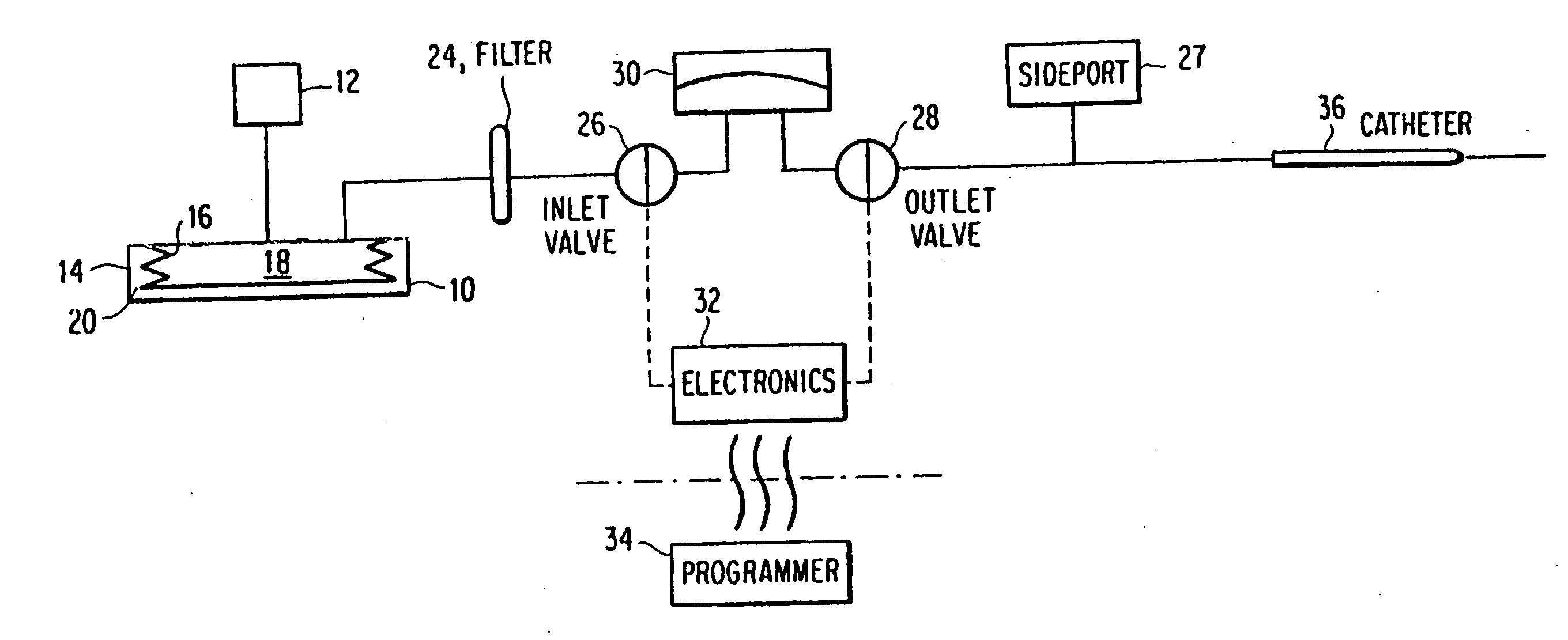
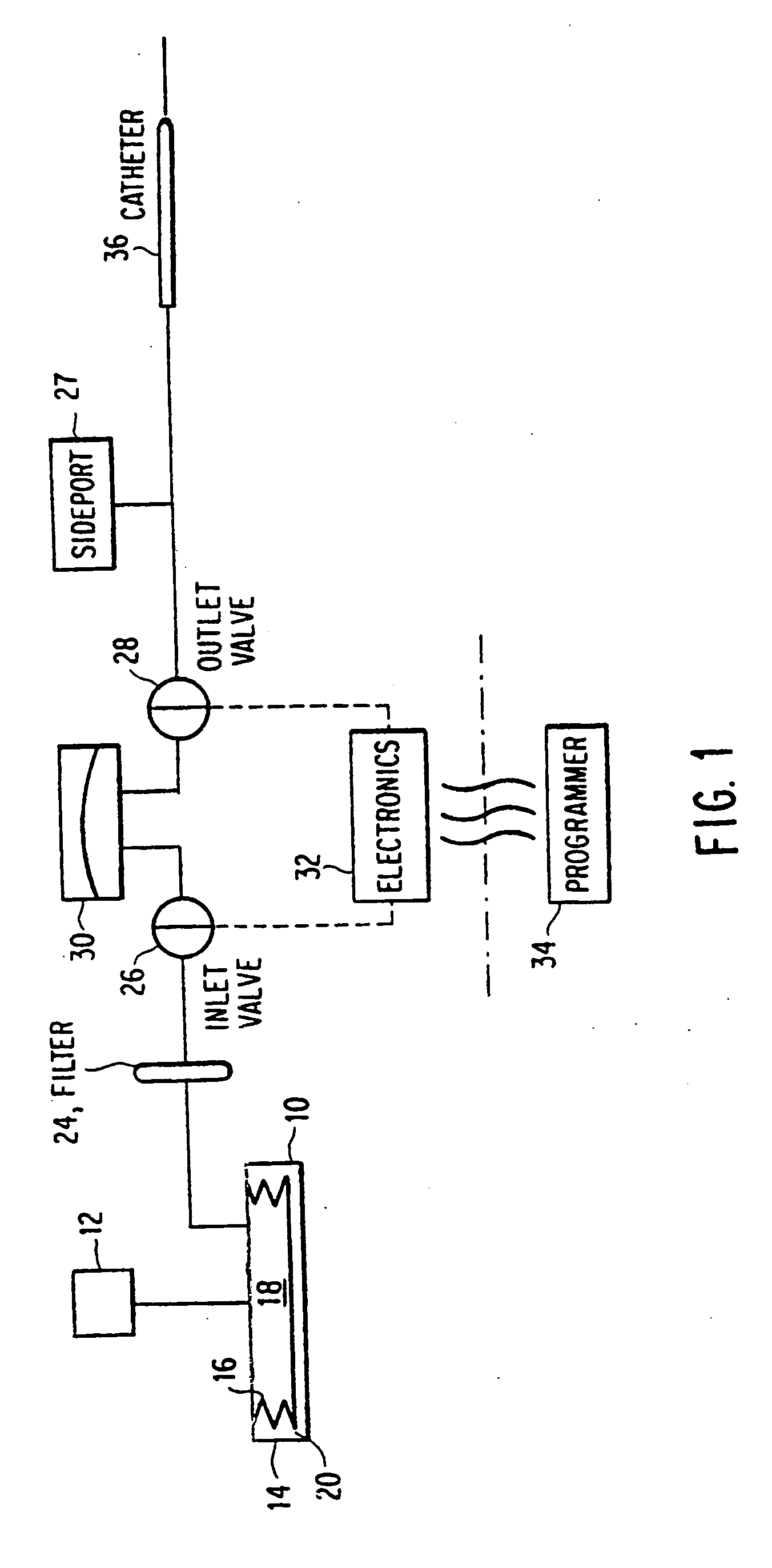
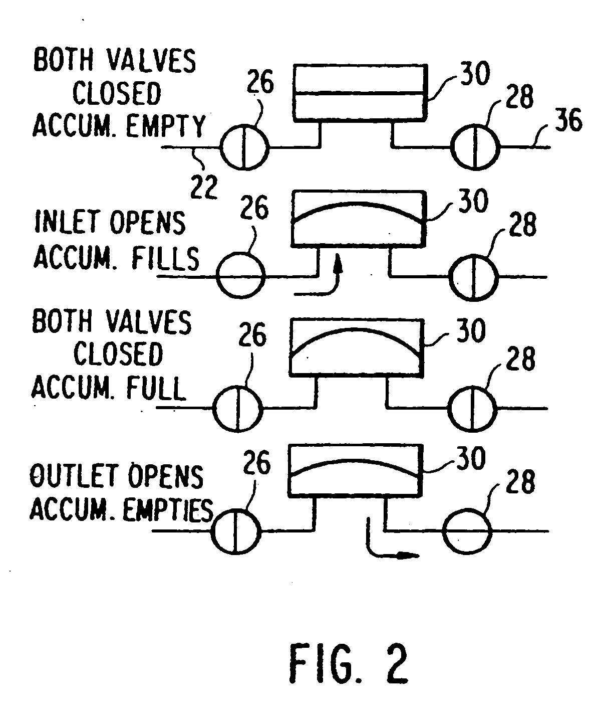
[0025]In a first embodiment, shown in FIG. 4, each solenoid is replaced with a single SMA wire. The valve system consists of two valves 110, 120, both in communication with an accumulator 130. The normal or default state of both valves is closed, and each is independently actuated using a respective SMA wire 112, 122. As done in the prior art, the inlet valve 116 is actuated to allow the passage of fluid through the inlet 140 and into the accumulator 130. The accumulator is preferably pressurized with a fluid, such as Argon (Ar) gas. Once the accumulator 130 reaches a maximum volume, such as about 2 μL, the inlet valve 116 can be closed. After the inlet valve 116 has been closed for a period of time, the outlet valve 126 can be safely actuated to allow the accumulator 130 to drain through the outlet valve 126 and through the outlet 150. The device follows the sequence of steps described in FIG. 2.

[0026]Each valve is actuated using a respective SMA wire 112, 122. These wires are pref...

Example

[0032]FIG. 6 shows a third embodiment of the assembly of the present invention. In this embodiment, the actuated member is a plunger 310, 320, and is surrounded by an elastic material 330, 332, such as an elastomer. Silicone or a soft plastic material, such as urethane can also be used. The plunger and the surrounding material is sized and shaped such that under normal conditions, the elastic material is under slight compression so as to force the valve seat closed. The plunger and elastic material also serve as a flexible fluid barrier. A SMA wire 312,322, in either a straight or looped configuration, is attached to the bottom of the plunger 310, 320.

[0033]When the SMA wire 312, 322 is energized and contracts, the plunger is pulled away from the valve seat. This causes the elastic material to deflect and allows the valve seat to open, thereby allowing fluid flow. When the current through the SMA wire 312, 322 is removed, the wire relaxes to its original length. The spring force fro...


PUM


Abstract

An implantable drug delivery system utilizing a non-magnetic valve/accumulator metering assembly is disclosed. The solenoids of the prior art, which respond to magnetic fields, are replaced by Shape Memory Alloy (SMA) wires and associated control electronics. By exploiting the inherent characteristics of SMA wires, which can expand and contract based on their temperature, the movements required to actuate the metering assembly can be achieved. This configuration retains the benefits associated with the prior art, while eliminating the major drawback.

Description

BACKGROUND OF THE INVENTION[0001]Implantable valve accumulator pump systems for the delivery of mediation or other fluids to a patient are well known and described in U.S. Pat. Nos. 4,838,887 and 5,049,141, the disclosures of which are hereby incorporated by reference.[0002]U.S. patent Nos. '887 and '141 disclose an implantable valve accumulator pump system for the delivery of infusate, such as medication. The implantable pump portion is comprised of four essential assemblies, as shown in FIG. 1. The first major assembly is a rechargeable, constant pressure drug reservoir 10 in series with a bacteria / air filter 24. In one embodiment, the reservoir 10 comprises a sealed housing 14 containing a bellows 16. The bellows 16 separates the housing 14 into two parts. Chamber 18 is used to hold the drug or other medicinal fluid. Second zone 20 is normally filled with a two-phase fluid, such as Freon®, that has a significant vapor pressure at body temperature. Thus, as the fluid within the se...

Claims


Application Information

Patent Timeline
IPC IPC(8): F04B49/00
CPCA61M5/14276A61M5/1483A61M5/16809G01F11/08F04B43/04F04B45/02A61M2205/0266
Inventor MCNALLY, JASONMORRISON, DAVIDMATCHEY, CONSTANTIN
Owner FLO(ABC) LLC
Why Eureka
Try Eureka