Method and apparatus for orienting magnetic flakes

a magnetic flakes and orientation technology, applied in the field of aligning or orienting magnetic flakes, can solve the problems of not widely known optically variable devices intended to be noticed, limited optical effects of “drawing” method, and inability to form “rolling-bar” and “flip-flop” images using this method

Active Publication Date: 2010-01-28
VIAVI SOLUTIONS INC
View PDF10 Cites 30 Cited by
  • Summary
  • Abstract
  • Description
  • Claims
  • Application Information

AI Technical Summary

Benefits of technology

[0023]Another feature of the present invention provides a screen within the apparatus so as to protect the flakes from the effect of the solidifying / currying means during the aligning step of the aforementioned method.

Problems solved by technology

Unfortunately, some optically variable devices that are intended to be noticed are not widely known because the optically variable aspect of the device is not sufficiently dramatic.
However, Richter uses a moving system and requires “drawing” of the image.
The “drawing” method provides only limited optical effects.
In particular, the “rolling-bar” and the “flip-flop” images can not be formed using this method.
This method, as well as “drawing”, takes time and is not conducive to production type processes.
Such features attract a person's attention, are easy to verify and difficult to forge, thus they are used more extensively over time in different applications, such as currency, documents, packaging.

Method used


Image

  • Method and apparatus for orienting magnetic flakes
  • Method and apparatus for orienting magnetic flakes
  • Method and apparatus for orienting magnetic flakes

Examples


Embodiment Construction

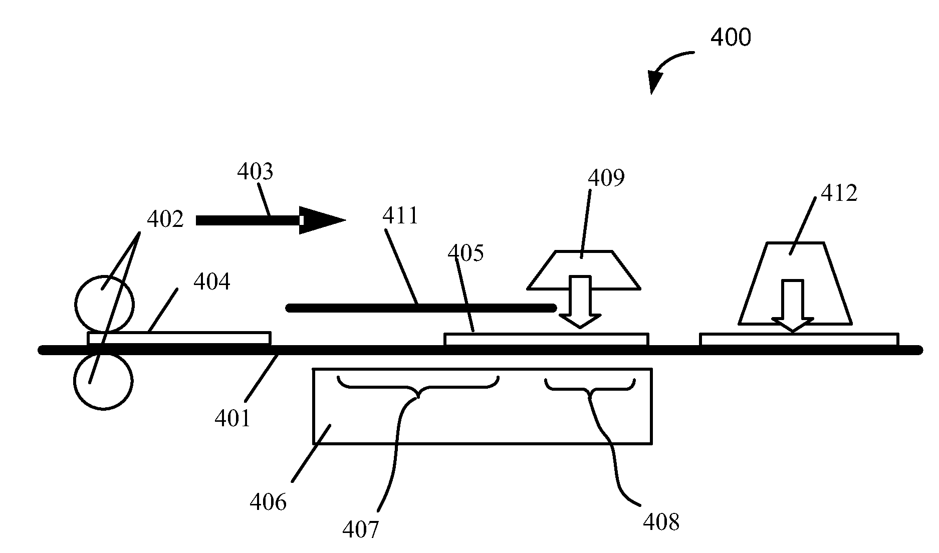
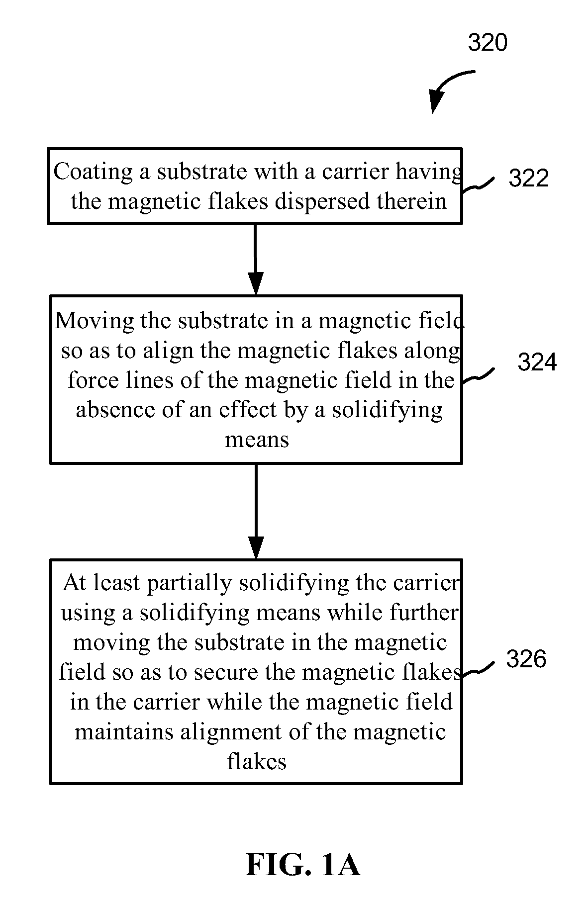
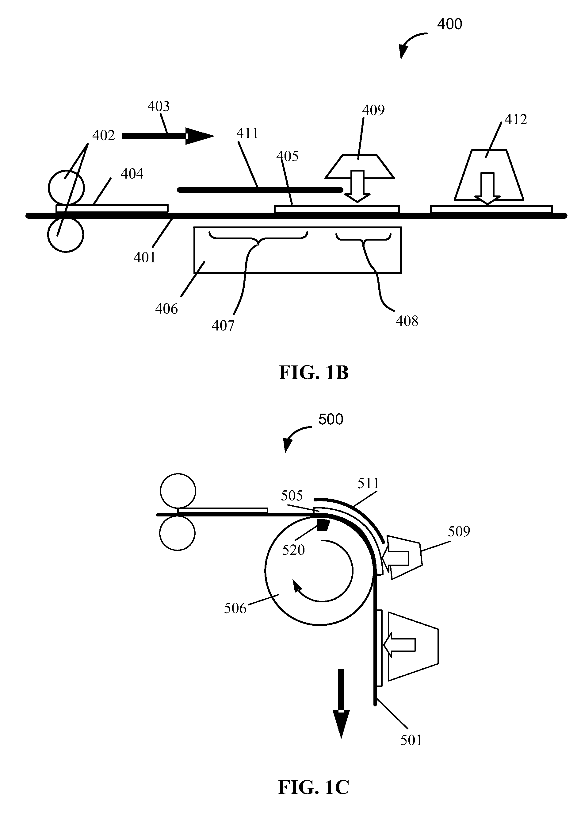
[0059]The present invention in its various embodiments solves the problem of pre-determined orientation of magnetic flakes of optically variable ink in a high-speed printing process. Normally, particles of an optically variable pigment dispersed in a liquid paint or ink vehicle generally orient themselves to be substantially parallel to the surface when printed or painted on to a surface. Orientation of reflective flakes parallel to the surface provides high reflectance of incident light from the coated surface. Magnetic flakes can be tilted while in the liquid medium by applying a magnetic field. The flakes generally align in such way that the longest diagonal of a flake follows a magnetic field line. Depending on the position and strength of the magnet, the magnetic field lines can penetrate the substrate at different angles, tilting magnetic flakes to these angles. A tilted reflective flake reflects incident light differently than a reflective flake that is parallel to the surfac...


PUM

PropertyMeasurementUnit
thickaaaaaaaaaa
thickaaaaaaaaaa
thickaaaaaaaaaa

Abstract

The invention relates to a method of aligning magnetic flakes, which includes: coating a substrate with a carrier having the flakes dispersed therein, moving the substrate in a magnetic field so as to align the flakes along force lines of the magnetic field in the absence of an effect from a solidifying means, and at least partially solidifying the carrier using a solidifying means while further moving the substrate in the magnetic field so as to secure the magnetic flakes in the carrier while the magnetic field maintains alignment of the magnetic flakes. An apparatus is provided, which has a belt for moving a substrate along a magnet assembly for aligning magnetic flakes. The apparatus also includes a solidifying means, such as a UV- or e-beam source, and a cover above a portion of the magnet assembly for protecting the flakes from the effect of the solidifying means.

Description

CROSS-REFERENCE TO RELATED APPLICATIONS[0001]The present patent application is a continuation-in-part from U.S. patent application Ser. No. 11 / 313,165 filed Dec. 20, 2005, which is a continuation-in-part of U.S. patent application Ser. No. 11 / 022,106 filed Dec. 22, 2004, now issued U.S. Pat. No. 7,517,578, which is a continuation-in-part of U.S. patent application Ser. No. 10 / 386,894 filed Mar. 11, 2003, now issued U.S. Pat. No. 7,047,883, which claims priority from U.S. Provisional Patent Application Ser. No. 60 / 410,546 filed Sep. 13, 2002, from U.S. Provisional Patent Application Ser. No. 60 / 410,547 filed Sep. 13, 2002, and from U.S. Provisional Patent Application Ser. No. 60 / 396,210 filed Jul. 15, 2002, the disclosures of which are hereby incorporated herein by reference in their entirety for all purposes.[0002]The present application is a continuation-in-part from U.S. patent application Ser. No. 11 / 623,190 filed Jan. 15, 2007, which claims priority from U.S. Provisional Patent ...

Claims


Application Information

Patent Timeline
Patent Type & Authority Applications(United States)
IPC IPC(8): B05D3/00B05D3/14B05D5/06B41M1/10B05D5/12B05D7/24B41M1/12B41M3/14B42D15/00B42D15/10
CPCB05D3/207B05D5/06B05D5/061B41F11/02B41M3/00B42D25/29B41M5/00B41P2200/30B42D2033/16B42D2035/20B41M3/14B42D25/369B41M1/00B41F23/00
Inventor RAKSHA, VLADIMIR P.COOMBS, PAUL G.MARKANTES, CHARLES T.
Owner VIAVI SOLUTIONS INC
Why Eureka
Try Eureka