Method for manufacturing electrophotographic photosensitive member

a photosensitive member and electrophotography technology, applied in the direction of electrographic process apparatus, instruments, corona discharge, etc., can solve the problems of difficult to reduce power consumption, difficult problem for conventional electrophotographic photosensitive member and electrophotographic apparatus, letter blur, etc., to reduce moisture adsorption, enhance hardness, and enhance abrasion resistance

Inactive Publication Date: 2010-01-28
CANON KK
View PDF15 Cites 18 Cited by
  • Summary
  • Abstract
  • Description
  • Claims
  • Application Information

AI Technical Summary

Benefits of technology

[0031]An object of the present invention is to provide the above described realization technique. Specifically, an object of the present invention is to provide a method for manufacturing an electrophotographic photosensitive member having superior characteristics of the electrophotographic photosensitive member, which realizes the inhibition of a high-humidity flow by reducing the adsorption of moisture and an electrification product on the surface of the electrophotographic photosensitive member, while enhancing abrasion resistance by enhancing the hardness and reducing energy consumption.

Problems solved by technology

However, a surface layer conventionally formed from a-SiC (hereinafter referred to as “a-SiC surface layer” as well) has occasionally caused a problem that when used in an environment of high absolute humidity, letters are blurred or the letters form a blank area without being printed (hereinafter referred to as “high-humidity flow”).
However, the heater for heating the photosensitive member needs a large amount of an electric power, so that when the heater for heating the photosensitive member is used, it is difficult to reduce the power consumption.
From the above description, it has been a very difficult problem for a conventional electrophotographic photosensitive member and electrophotographic apparatus to realize both of enhancing the abrasion resistance and reducing the power consumption while inhibiting the high-humidity flow.
In addition, there is a case in which hydrogen atoms are overly reduced in the surface layer by an excessive decomposition of the source gas depending on a manufacturing condition, even when the C / (Si+C) of the a-SiC surface layer is controlled to an appropriate range.
In such a case, it becomes difficult to keep the sensitivity adequate.
As was described above, it has been very difficult to prepare the a-SiC surface layer having all of high-humidity flow, an abrasion amount, gradation properties and sensitivity controlled to an adequate state, and the realization technique has not been found.

Method used


Image

  • Method for manufacturing electrophotographic photosensitive member
  • Method for manufacturing electrophotographic photosensitive member
  • Method for manufacturing electrophotographic photosensitive member

Examples


example 1

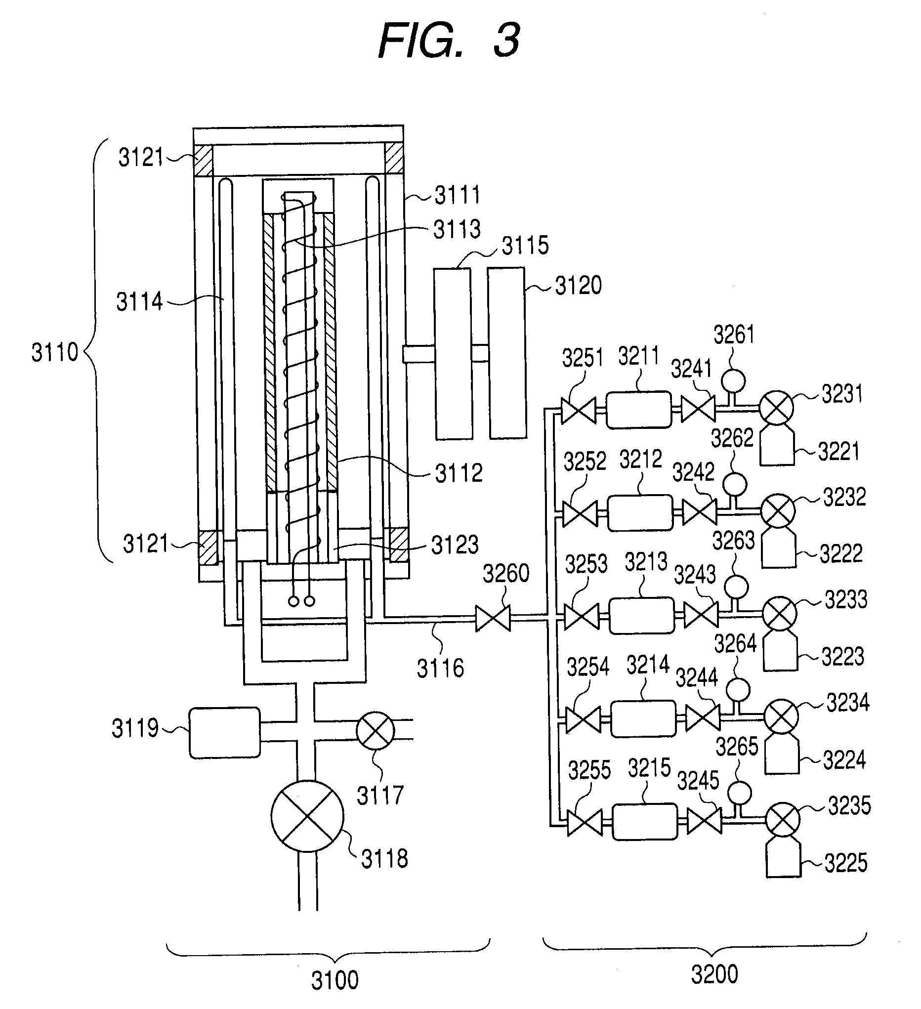
[0096]A positively chargeable a-Si photosensitive member was prepared by forming each layer on a conductive substrate (cylindrical substrate made from aluminum, which has diameter of 80 mm, length of 358 mm and thickness of 3 mm, and has been mirror-finished) by using a plasma treatment apparatus with the use of a high-frequency power source with an RF range as illustrated in FIG. 3, on conditions shown in the following Table 1 and Table 2. At this time, films of an electric-charge injection preventing layer, a photoconductive layer, a first surface layer and a second surface layer were formed (layer formation), in this order, and a film-forming period of time was controlled so that the film thicknesses of the layers could be respective values in Table 1. In addition, two electrophotographic photosensitive members were prepared for each film-forming condition.

TABLE 1electric-chargeinjectionphoto-firstsecondpreventingconductivesurfacesurfacelayerlayerlayerlayergas type and flow rateS...

example 2

[0142]Positively chargeable a-Si photosensitive members were prepared by forming each layer on the same conductive substrate as the above described one, by using a plasma treatment apparatus with the use of a high-frequency power source with an RF range as illustrated in FIG. 3, in conditions shown in the following Table 6 and Table 7. At this time, films of an electric-charge injection preventing layer, a photoconductive layer, a first surface layer and a second surface layer were formed (layer formation), in this order, and film-forming periods of time were controlled so that the film thicknesses of the layers could be respective values in Table 6. In addition, two electrophotographic photosensitive members were prepared for each film-forming condition.

TABLE 6electric-chargeinjectionphoto-firstsecondpreventingconductivesurfacesurfacelayerlayerlayerlayergas type and flow rateSiH4 [mL / min (normal)]3504502525H2 [mL / min (normal)]7502200B2H6 [ppm ] (w.r.t. SiH4)15001NO [mL / min (normal)...

example 3

[0148]Positively chargeable a-Si photosensitive members were prepared by forming each layer on the same conductive substrate as the above described one, by using a plasma treatment apparatus with the use of a high-frequency power source illustrated in FIG. 3, which uses RF frequencies, in conditions shown in the following Table 10 and Table 11. At this time, films of an electric-charge injection preventing layer, a photoconductive layer, a first surface layer and a second surface layer were formed (layer formation) in this order, and a film-forming period of time was controlled so that the film thicknesses of the layers could be respective values in Table 10. In addition, two electrophotographic photosensitive members were prepared for each film-forming condition.

[0149]In the present example, a second joining layer is provided in between the first surface layer and the second surface layer. The electrophotographic photosensitive member (positively chargeable a-Si photosensitive memb...


PUM


Abstract

The present invention provides a method for manufacturing an electrophotographic photosensitive member including: forming a first surface layer and a second surface layer of the electrophotographic photosensitive member by supplying a source gas into a reaction vessel so that C2/S2 which are respectively flow rates of CH4 and SiH4 flowing when the second surface layer is formed can be 3 or more and 25 or less, and C1/S1 which are respectively flow rates of CH4 and SiH4 flowing when the first surface layer is formed can be C2/S2 or more but 60 or less, and adjusting the high-frequency power so that P2>P1 can be satisfied which are high-frequency powers respectively when the second surface layer is formed and when the first surface layer is formed, and C/(Si+C) of the first surface layer and C/(Si+C) of the second surface layer can be 0.50 or more and 0.80 or less.

Description

BACKGROUND OF THE INVENTION[0001]1. Field of the Invention[0002]The present invention relates to a method for manufacturing an electrophotographic photosensitive member (hereinafter referred to as “a-Si photosensitive member” as well) having a photoconductive layer (hereinafter referred to as “a-Si photoconductive layer” as well) formed from amorphous silicon (hereinafter referred to as “a-Si” as well), which can be applied to an image-forming apparatus (electrophotographic apparatus) using an electrophotographic process such as a copying machine, a printer and a facsimile.[0003]2. Description of the Related Art[0004]An electrophotographic photosensitive member is widely known, which is made by forming a photoconductive layer (photosensitive layer) consisting of an amorphous material on a conductive substrate (hereinafter referred to as merely “substrate” as well). An a-Si photosensitive member has already been commercialized, which has a photoconductive layer formed on the substrat...

Claims


Application Information

Patent Timeline
Patent Type & Authority Applications(United States)
IPC IPC(8): G03G5/08
CPCG03G5/08278G03G5/08242
Inventor OZAWA, TOMOHITOAKIYAMA, KAZUYOSHINISHIMURA, YUU
Owner CANON KK
Why Eureka
Try Eureka