Storage device and control method for the same

Active Publication Date: 2010-01-28
HITACHI LTD
View PDF7 Cites 45 Cited by
  • Summary
  • Abstract
  • Description
  • Claims
  • Application Information

AI Technical Summary

Benefits of technology

[0015]According to the invention, proposed is a storage device that can achieve reduction of power consumption, simplificat

Problems solved by technology

In such a configuration, if the storage capacity of a pool is not entirely used, i.e., not allocated as a virtual volume, as is provided large in advance, the pool volumes providing such unused storage areas also have to be always in operation, thereby increasing the power consumption.
Another problem here is that, once created, the storage capacity of a pool cannot be reduced even if the pool is found out as not

Method used


Image

  • Storage device and control method for the same
  • Storage device and control method for the same
  • Storage device and control method for the same

Examples


Example

First Embodiment

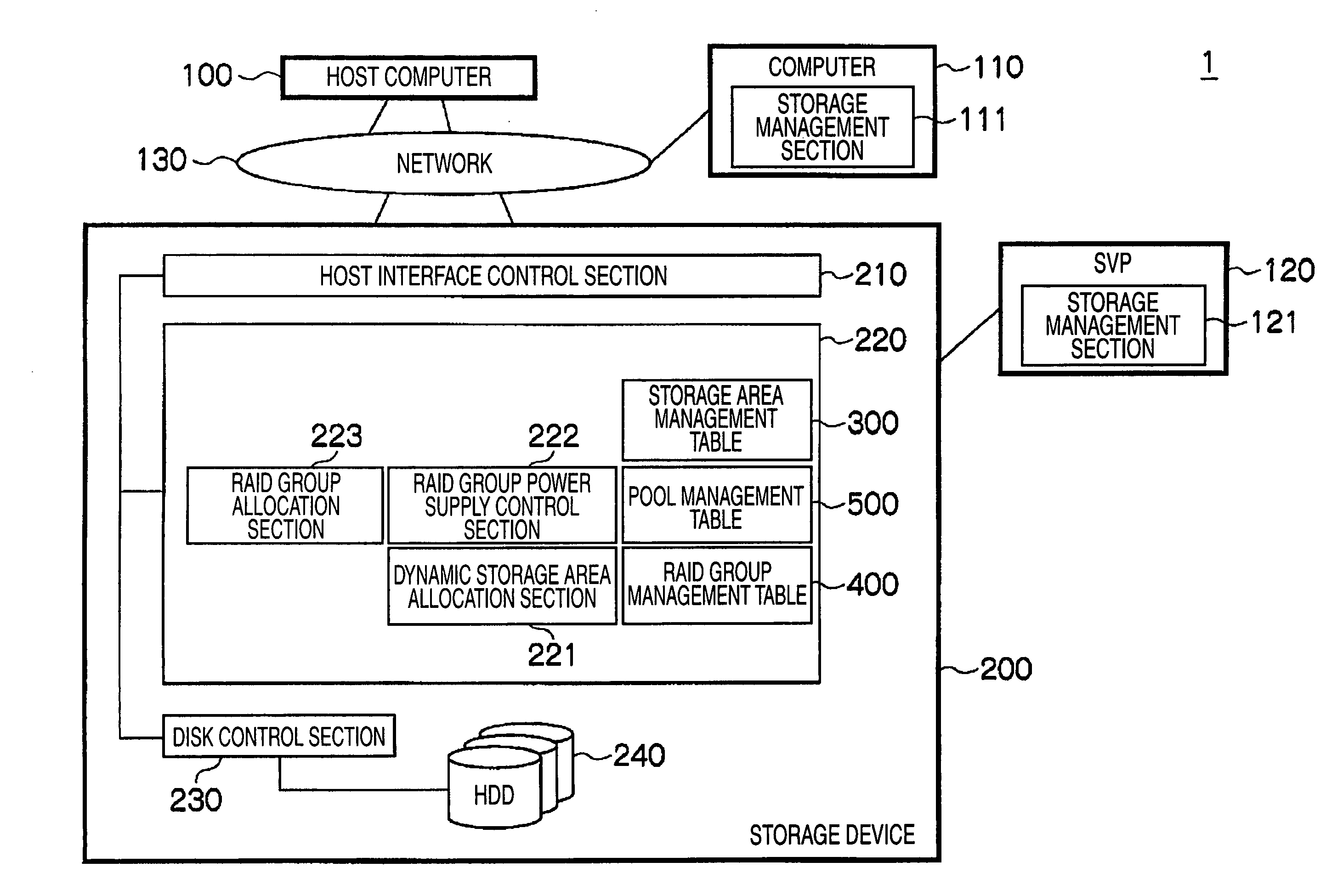
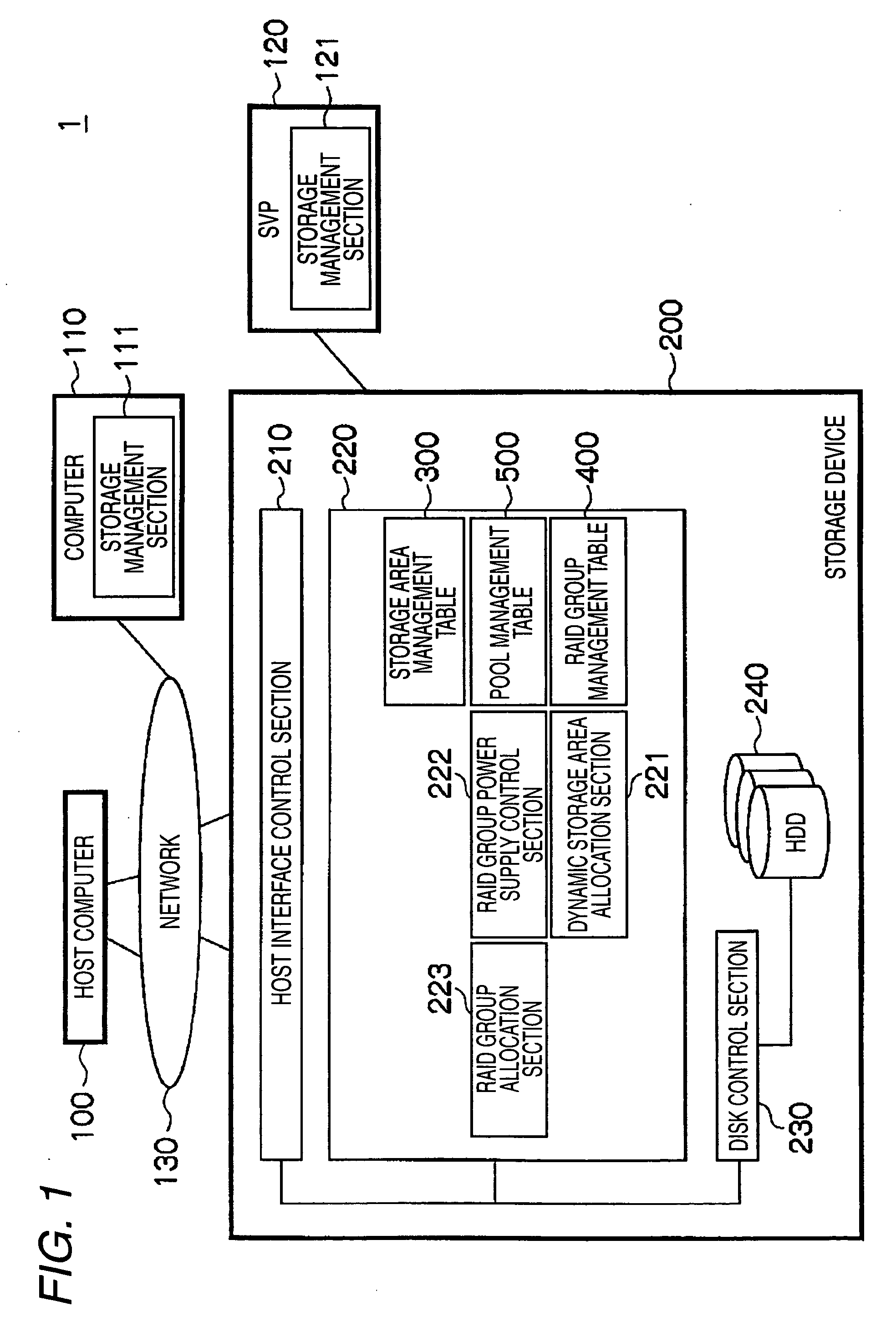
[0035]FIG. 1 is a diagram showing the entire configuration of a storage system. As shown in FIG. 1, a storage system 1 is configured to include a host computer 100, a computer 110, a maintenance terminal (SVP) 120, and a storage device 200. Among these components, i.e., the host computer 100, the computer 110, and the storage device 200, a connection is established over a network 130. The maintenance terminal 120 is connected to the storage device 200.

[0036]The host computer 100 executes various operations by running an application program (not shown), and stores the result in the storage device 200. That is, the host computer 100 writes data of operation results into the storage device 200 over the network 130, and when necessary, reads thus written data from the storage device 200.

[0037]The computer 110 manages the storage device 200 connected to the network 130. The maintenance terminal 120 is provided for maintenance use of the storage device 200. The computer 11...

Example

Second Embodiment

[0111]Exemplified in the first embodiment is the case that the pool reduction process is executed automatically. Alternatively, an operator may be notified of any RAID group to be reduced, and the reduction process may be executed in response to a command issued by the operator.

[0112]FIG. 17 is a diagram showing an exemplary screen display of a pool management screen at the time of RAID group reduction. This screen display 600 is to be displayed at the time of the RAID group reduction process that will be described later. This pool management screen may be displayed on the computer 110, or on the maintenance terminal 120.

[0113]The screen display 600 includes a table 600 and a detailed information area 610. The table 600 displays potential RAID group(s) to be reduced, and the detailed information area 610 displays the detailed information of the RAID group(s).

[0114]The table 600 includes a designation field 611, a RAID group number field 612, an LU number field 613, ...


PUM


Abstract

A storage device is provided with: a first management section that manages a storage area provided by one or more hard disk drives on a basis of a predetermined unit created using one or more parameters; a second management section that manages, on a basis of a pool configured by at least one or more of the units, a management policy about the capacity of the pools and a threshold value of the storage capacity of the pools; a power supply control section that controls each of the hard disk drives of the unit under the management of the first management section to be in either a first turn-ON state or a second turn-ON state with a low power consumption; and a control section that selects, when the storage capacity of any of the pools exceeds the threshold value, the management policy of the pools, and any of the managed parameters considered optimum to serve as the unit of the storage area, and after making the power supply control section to change the state of the hard disk drive of the selected unit from the second turn-ON state to the first turn-ON state, adds the unit of the storage area to the capacity of the pool. With such a configuration, the storage device can achieve reduction of power consumption, simplification of management, and increase of use efficiency of storage resources.

Description

CROSS REFERENCES TO RELATED APPLICATIONS[0001]This application relates to and claims priority from Japanese Patent Application No. 2008-193724, field on Jul. 28, 2008, the entire disclosure of which is incorporated herein by reference.BACKGROUND OF THE INVENTION[0002]1. Field of the Invention[0003]The present invention relates to a storage device and a control method therefor and, more specifically, is suitable when it is applied to a storage device storing data utilizing virtual volumes, and a method for controlling such a storage device.[0004]2. Description of the Related Art[0005]With a well-known technology for a storage system, virtual volumes consuming no physical storage area are defined, these virtual volumes are provided to a server, and allocation of the physical storage areas is performed at the time of actual data writing from the server, thereby increasing the use efficiency of the storage capacity of a storage device.[0006]In another type of storage system, for increas...

Claims


Application Information

Patent Timeline
IPC IPC(8): G06F12/00G06F1/32G06F1/26
CPCG06F1/3221G06F1/3268G06F3/0625G06F3/0644Y02B60/1246G06F3/0665G06F3/0689G11B19/209G06F3/0649Y02D10/00Y02D30/50
Inventor IKEJIRI, KEITAROINNAN, MASATAKATABUCHI, HIDEO
Owner HITACHI LTD
Why Eureka
Try Eureka