

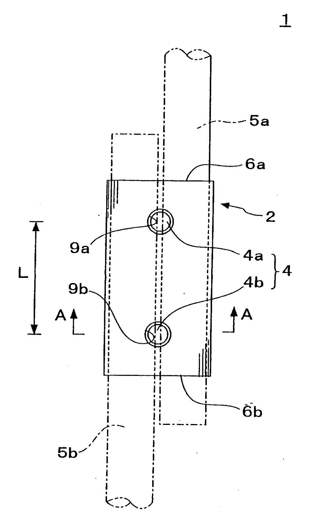
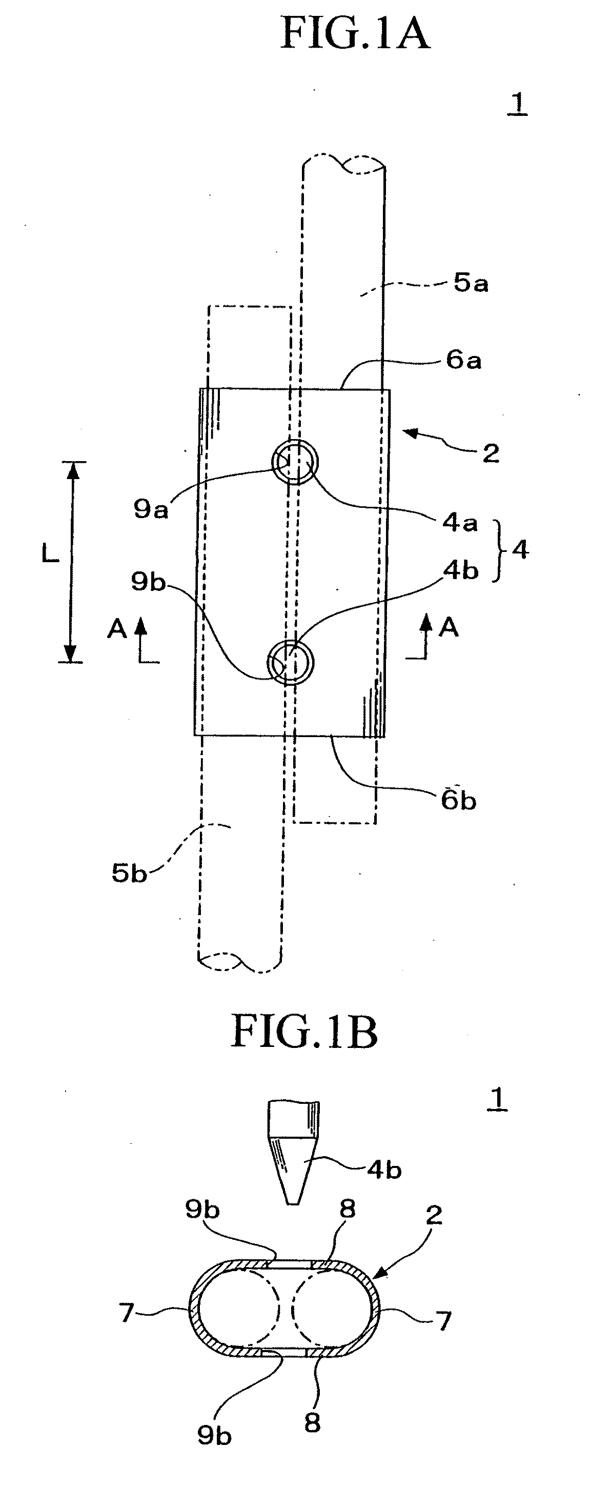
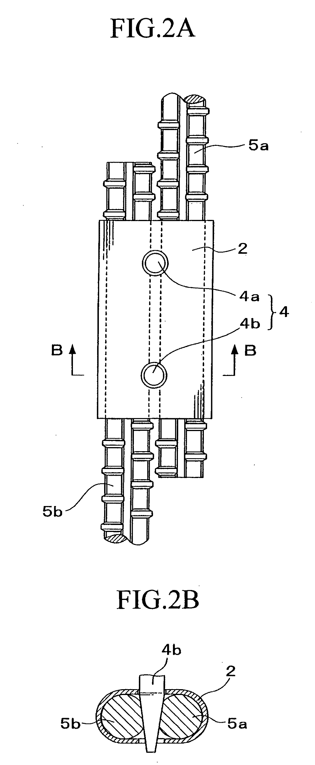
Reinforcing bar joint
a technology of reinforcing bars and joints, applied in the direction of building reinforcements, constructions, building components, etc., can solve the problems of increasing the diameter of the bar, the insufficient versatility of the bar pitch, and the difficulty in performing various bar arrangements or secure overlapping lengths, so as to reduce the bending deformation, and increase the distance between the points of action of the tensile forces acting on the reinforcing bars
- Summary
- Abstract
- Description
- Claims
- Application Information
AI Technical Summary
Benefits of technology
Problems solved by technology
Method used
Image

Examples
example 1
[0074]Table 1 shows the results of a tensile test. The tensile test used reinforcing bars of steel type SD345 (concrete reinforcing steel rod, Japanese Industrial Standard, specification values of 345 N / mm2 in yield point and 490 N / mm2 in tensile strength), having a diameter of D22 (nominal cross-sectional area of 387.1 mm2). In the cases where two holes were provided, the holes were spaced 50 mm apart. The same holds for the tests to be described hereinafter.
[0075][Table 1]
TABLE 1SleeveTest resultYieldTensileThick-NumberSectionalYieldMaximumMaximumpointstrengthLengthnessofareastrengthstrengthtensileTestSteelsσysσusLstholessAsPysPustrengthpiecetype(N / mm2)(N / mm2)(mm)(mm)sn(mm2)(kN)(kN)(kN)Final condition1STKM2153701004.02586.1126.0216.9180.0Split213A1501157.5Pulling out32225.0Base-material fracture410010.021599.6343.9591.8224.0Base-material fracture5S45C3255101005.01719.4233.8366.9175.4Pulling out62208.4Base-material fracture71004.52654.5212.7333.8176.2Split Wedge break204.681202216....
example 2
[0084]Table 2 shows the results of another tensile test. In the table, pulling out refers to a shear fracture of a reinforcing bar at a position where a wedge member bites into (an area of, chipped section). A split refers to a splitting fracture of a sleeve end in contact with a reinforcing bar. A wedge break refers to a breakage of a reinforcing bar at a position where a wedge member bites into (an area of chipped section).
[0085]The tensile test used reinforcing bars of steel type SD390 (concrete reinforcing steel rod, Japanese Industrial Standard, specification values of 390 N / mm2 in yield point and 560 N / mm2 in tensile strength), having a diameter of D22. If a test result included variations, the plurality of results is shown in the “test result” field.
[0086][Table 2]
TABLE 2SleeveTensileTensilestrengthstrengthNumberTestSteel(spec)(material)LengthThicknessofExperimental tensile strengthpiecetype(N / mm2)(N / mm2)(mm)(mm)holesTest resultMaterial tensile strength9S45C510679.41004.532We...
PUM
 Abstract
Description
Claims
Application Information