Pneumatic tire for two-wheeled vehicle

a two-wheeled vehicle and pneumatic technology, applied in the direction of tyre beads, bicycles, transportation and packaging, etc., can solve the problems of unfavorable driving stability and dramatic improvement of driving stability, and achieve the effect of reducing the rigidity of the belt in the plane, reducing the amount of belt force when turning, and reducing the force of the grip

Inactive Publication Date: 2010-02-04
BRIDGESTONE CORP
View PDF7 Cites 3 Cited by
  • Summary
  • Abstract
  • Description
  • Claims
  • Application Information

AI Technical Summary

Benefits of technology

[0020]The width of the spiral belt layer is preferably in the range of 0.7 L to 0.8 L and more preferably in the range of 0.75 L to 0.8 L.
[0021]Further, in the first aspect the presence of an intersecting belt layer in at least a portion of both left and right side shoulder portions, which have a width of 0.15 L to 0.35 L and at which the spiral belt layer is not formed, is specified. If the intersecting belt layer is not present at that portion, the in-plane shear rigidity of the belt is reduced, the belt is excessively weak, and grip force when turning is easily reduced. Further, high rigidity can be maintained at the tread center portion as the spiral belt is wound therefore, there are no problems even if the intersecting belt layer does not exist at the center portion.
[0022]Further, in the first aspect, the cord angle of the intersecting belt layer is set at from 30° to less than 75° relative to the tire circumferential direction. If the cord angle is less than 30° relative to the tire circumferential direction (equatorial direction), the angle approaches that of the spiral belt layer, resulting in inhibiting stretching of the intersecting belt in the tire circumferential direction (equatorial direction). In such a case, conversely to the purpose of the invention of stretching the belt at the ground contact portion of the shoulder portion in the equatorial direction, the frame member at the tread shoulder is inhibited from stretching in the equatorial direction and it becomes difficult to increase the belt portion velocity at the tread shoulder. Accordingly, the deformation in the braking state is maintained at the tread shoulder portion and traction grip is impaired and, in addition, uneven wear is liable to occur. Further, if the cord angle of the intersecting belt layer exceeds 75°, a sufficient intersection effect, that is an effect whereby the in-plane shear rigidity of the belt is increased by superimposing belts having mutually opposite directions, cannot be achieved by the intersecting belt layer, the in-plane shear rigidity of the intersecting belt layer is insufficient, and sufficient grip cannot be obtained when turning. In addition, the angle is preferably 45° or more as this facilitates stretching of the frame member in the equatorial direction. Further, the angle is preferably 70° or less in view of realization of in-plane shear rigidity.
[0023]Further, the cords included in the intersecting belt layer disposed at the shoulder portion are organic material fiber cords. This is because when cords such as steel cords, which also maintain rigidity in the compression direction of the cord, are arranged as the intersecting belt layer, the frame member is hard to be deformed outside, the ground contact portion becomes smaller, and grip force is reduced. With organic material fiber cords, the rigidity in the compression direction of the cord is small and the ground contact portion enlarged while antiplane rigidity of the frame member can be reduced. Because extremely robust rigidity is maintained in the cord tension direction, in-plane rigidity can be effectively increased.
[0024]Note that the material of the cords constituting the spiral belt layer may be steel or organic material fiber. This is because there is no risk that the antiplane bending rigidity of the belt will be increased more than necessary as the spiral belt layer is not intersecting. When a belt is made to intersect as at the shoulder portion, use of steel chords should be avoided. The material of the intersecting belt layer is preferably a fiber having high tensile rigidity and heat resistance such as aromatic polyamide (product name: Kevlar).
[0025]Further, the carcass (body ply, carcass ply) is at least one layer. In the case of one layer, it is usually disposed in a direction at an angle of 90° to the tire circumferential direction, that is, in the tire radial direction. In the case of two layers, two sheets may be layered in the radial direction, or they may be disposed at an angle of 70° relative to the tire circumferential direction so as to mutually intersect. Further, the method of engagement with the carcass bead portion may be done by winding around the bead core and folding back, or engagement by cutting the carcass at the leading end of the beads, disposing bead wire at both sides of the cord end portions, and nipping the carcass between the bead wires.

Problems solved by technology

There are cases in which high performance pneumatic tires for two-wheeled vehicles are greatly influenced by centrifugal force and prone to distension of the tire tread portion toward an outer side in the radial direction of the tire due to high rotational velocity of the tire, which results in unfavorable driving stability.
However, as regards driving stability, in particular, tuning performance when a vehicle (for example, a motorcycle) is tilted low, it cannot be said that the driving stability has been dramatically improved simply because reinforcing members (spiral members) have been wound around.

Method used


Image

  • Pneumatic tire for two-wheeled vehicle
  • Pneumatic tire for two-wheeled vehicle
  • Pneumatic tire for two-wheeled vehicle

Examples


example 1

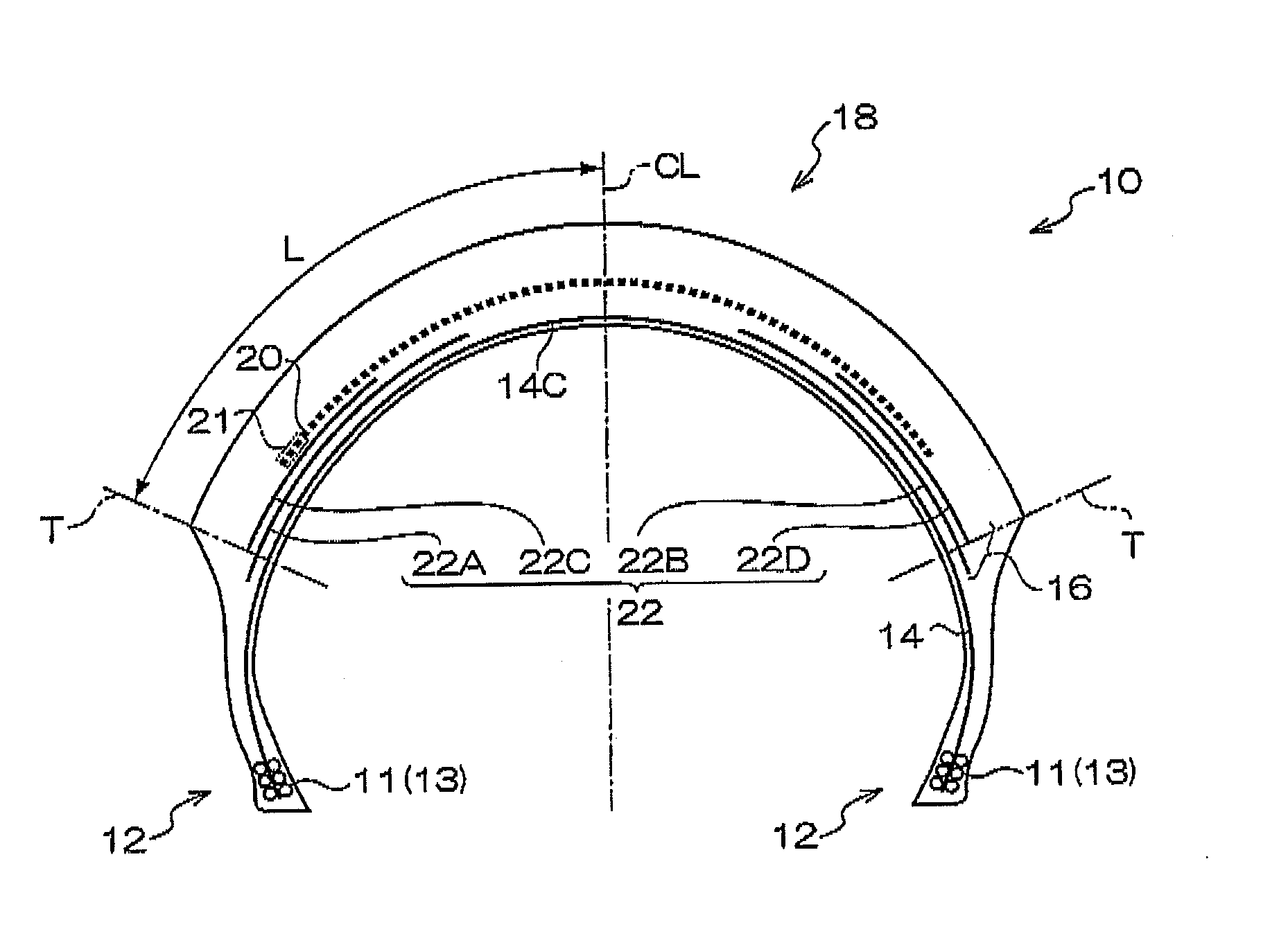
[0058]Example 1 is a pneumatic tire for a two-wheeled vehicle having the structure shown in FIG. 1. Spiral belt layer 20 is 180 mm wide (the width of one side thereof from the tire equatorial plane being 90 mm), which is 0.75 times the entire width of the tread 2 L. Spiral belt layer 20 is formed by spirally winding steel cords plied from 1×3 steel monofilaments each having a diameter of 0.18 mm, with 60 cords laid per 50 mm.

[0059]At an inner side of spiral belt layer 20 are two pairs of left and right symmetrical intersecting belts 22A-22D (intersecting belts 22A and 22C are one pair, and intersecting belts 22B and 22D are another pair). First intersecting belts 22A and 22B are each 80 nm wide, and tire width direction outer ends thereof extend 5 mm from tread end T toward a tire outer side. Second intersecting belts 22C and 22D are each 50 mm wide, and tire width direction outer ends thereof are at the same position as tread edge T. The first intersecting belts and the second inte...

example 2

[0061]Example 2 has a configuration in which one reinforcement belt (the same as reinforcement belt 34 described in Example 3 below) is added at a radial direction outer side of spiral belt layer 20 of Example 1 (see FIG. 1), at an angle of 90° relative to the tire circumferential direction. The added reinforcement belt is 240 mm wide, and is made from an aromatic polyamide. The material of the reinforcement belt is the same as that of conventional intersecting belts 82I and 82E, and the manner of laying the cords and the diameter of the cords are also the same; however, the cord angle thereof is 90°, which is different from the Conventional Example.

example 3

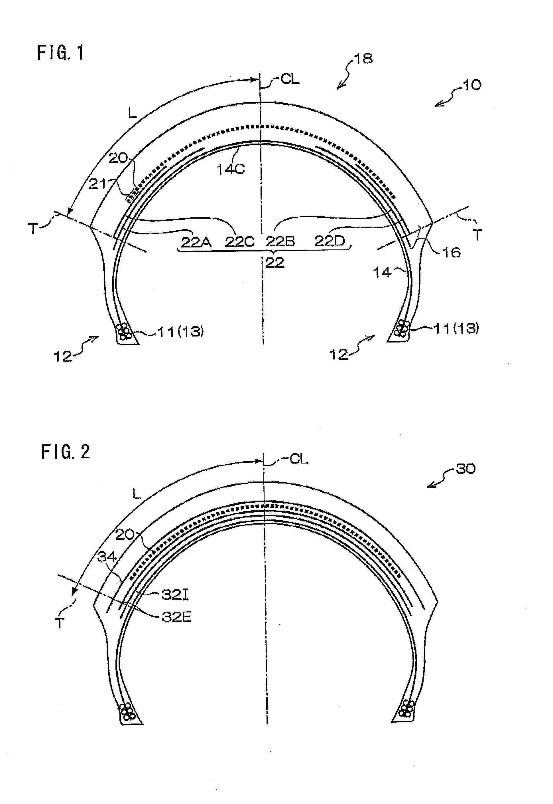
[0062]Example 3 is a pneumatic tire 30 for a two-wheeled vehicle having the structure shown in FIG. 2.

[0063]Example 3 includes the above spiral belt layer 20 and intersecting belts 32I and 32E similar to the Conventional Example. That is, first intersecting belt 32I is 240 mm wide, second intersecting belt 32E is 230 mm wide, and each has a cord angle of 65° relative to a tire circumferential direction. Similar to the other examples, the width of spiral belt layer 20 is 180 mm, which is different from spiral belt layer 80 of the Conventional Example. At a radial direction outer side of spiral belt layer 20 is a reinforcement belt 34 having a cord angle of 90°, similar to Example 2. Reinforcement belt 34 is 240 mm wide, the same as in Example 2. The cords of reinforcement belt 34 are made of Kevlar.


PUM


Abstract

A pneumatic tire for a two-wheeled vehicle has further increased driving stability, particularly in turning. Pneumatic tire 10 for a two-wheeled vehicle has belt layer 16 and tread section 18 that are sequentially arranged on the outer side, in the radial direction of the tire, of a crown section 14C of a carcass 14. On the belt layer 16 is placed a spiral belt layer 20 formed by spirally winding a band-like rubber coated cord layer so as to form a cord angle in the range of 0° to 5° relative to the circumferential direction of the tire. With L the tread surface distance from tire center CL to tread edge T, spiral belt layer 20 is present only in the range of 0.65 L to 0.85 L from tire center CL, and intersecting belt layers 22A-22D are arranged in the range of from an edge in the lateral direction of the spiral belt layer 20 to tread edge T. Intersecting belt layers 22A-22D include organic material fiber cords intersecting with each other and having a cord angle of from 30° to less than 75° relative to the circumferential direction of the tire.

Description

TECHNICAL FIELD[0001]The present invention relates to a pneumatic tire for a two-wheeled vehicle having high driving stability at high speed running and, more specifically, to a pneumatic tire that is optimized for two-wheeled vehicles in particular and which also has improved traction performance in deep cornering when the vehicle is tilted low.RELATED ART[0002]There are cases in which high performance pneumatic tires for two-wheeled vehicles are greatly influenced by centrifugal force and prone to distension of the tire tread portion toward an outer side in the radial direction of the tire due to high rotational velocity of the tire, which results in unfavorable driving stability. In order to prevent this, a tire structure has been developed in which reinforcing members (spiral members) of organic material fiber or steel are wound around at the tire tread portion so as to be substantially parallel to the tire equatorial plane. Nylon fiber, aromatic polyamide (Kevlar), steel and th...

Claims


Application Information

Patent Timeline
Patent Type & Authority Applications(United States)
IPC IPC(8): B60C9/00B60C13/00
CPCB60C9/2009B60C9/2204B60C9/28B60C2009/2041B60C15/0018B60C2200/10B60C11/0332
Inventor ISHIYAMA, MAKOTO
Owner BRIDGESTONE CORP
Why Eureka
Try Eureka