
Hose fitting

a technology for hoses and fittings, applied in the direction of hose connections, pipe/joints/fittings, pipe connection arrangements, etc., can solve the problems of end fittings, end fittings, and outer collars, which are costly both in processing time and materials, and can be reused. reusable end fittings, etc., to achieve the effect of reducing friction

Inactive Publication Date: 2010-02-04
AFLEX HOSE
View PDF9 Cites 11 Cited by
  • Summary
  • Abstract
  • Description
  • Claims
  • Application Information

AI Technical Summary

Benefits of technology

[0015]The present invention is advantageous over conventional concentric locking collars that comprise tapering in the region of compression for two reasons. Firstly, by utilising an outer collar and inner sleeve being devoid of a taper in the region of compression, the frictional locking force between the two mating surfaces obviates the need for an additional mechanical locking means which is otherwise required with conventional tapered collars and sleeves. The inner surface of the outer collar and inner and outer surfaces of the inner sleeve of the present invention are aligned substantially parallel to the longitudinal axis of the outer collar, inner sleeve and connection body such that the locking force between the inner sleeve and outer collar in the axial direction is substantially uniform. Secondly, the length of the outer collar and the inner is not limited as with conventional tapered systems in which the length of the collar and sleeve is limited by their relative increasing and decreasing wall thicknesses. The present invention in turn provides increased design flexibility and the possibility of increasing the strength of seal by increasing the length of collar and sleeve as required.
[0016]Through the cooperation between the outer collar and inner sleeve, the present invention is configurable to maintain a fluid tight seal between the end fitting and the hose up to the burst pressure of the hose. Additionally, the present invention is designed to allow easy land convenient release of the locking action provided by the outer collar and inner sleeve to enable extraction of the connection body from the hose for reuse. The outer collar is also designed to be reusable.
[0020]Further, the inner surface of the inner sleeve may comprise an annular groove configured to mate with an annular shoulder extending from the connection body, the cooperation between the groove and shoulder being configured to inhibit longitudinal displacement of the inner sleeve relative to the connection body.
[0021]The outer collar may comprise at least one or a plurality of recessed grooves or indented portions provided on its internal surface. Preferably, two annular grooves are formed at the internal surface of the outer collar, each groove being axially spaced from one another. The indented regions serve to reduce friction between the outer collar and the inner sleeve as the mating surfaces are brought together.
[0022]According to a further implementation, the inner sleeve comprises a shoulder extending from its inner surface configured to mate with a shoulder extending from the connection body. The shoulders are mated to abut one another as the inner sleeve is compressed radially through frictional contact with the outer collar. The interlocking shoulders of the connection body and inner sleeve serve to inhibit longitudinal displacement of the inner sleeve relative to the connection body.
[0030]Optionally, to decrease the frictional contact between the outer collar and the inner sleeve so as to ease the assembly operation but not compromise integrity of the resulting joint, the inner surface of the outer collar may have internal radial grooves cut into it thereby reducing the surface area in contact with the inner sleeve.

Problems solved by technology

There are a number of disadvantages associated with conventional reusable end fittings.
The implementation of mechanical locking means necessitates additional machining and processing of both the end fitting and the outer collar which is costly both in terms of processing time and materials.

Method used


Image

  • Hose fitting
  • Hose fitting
  • Hose fitting

Examples


Embodiment Construction

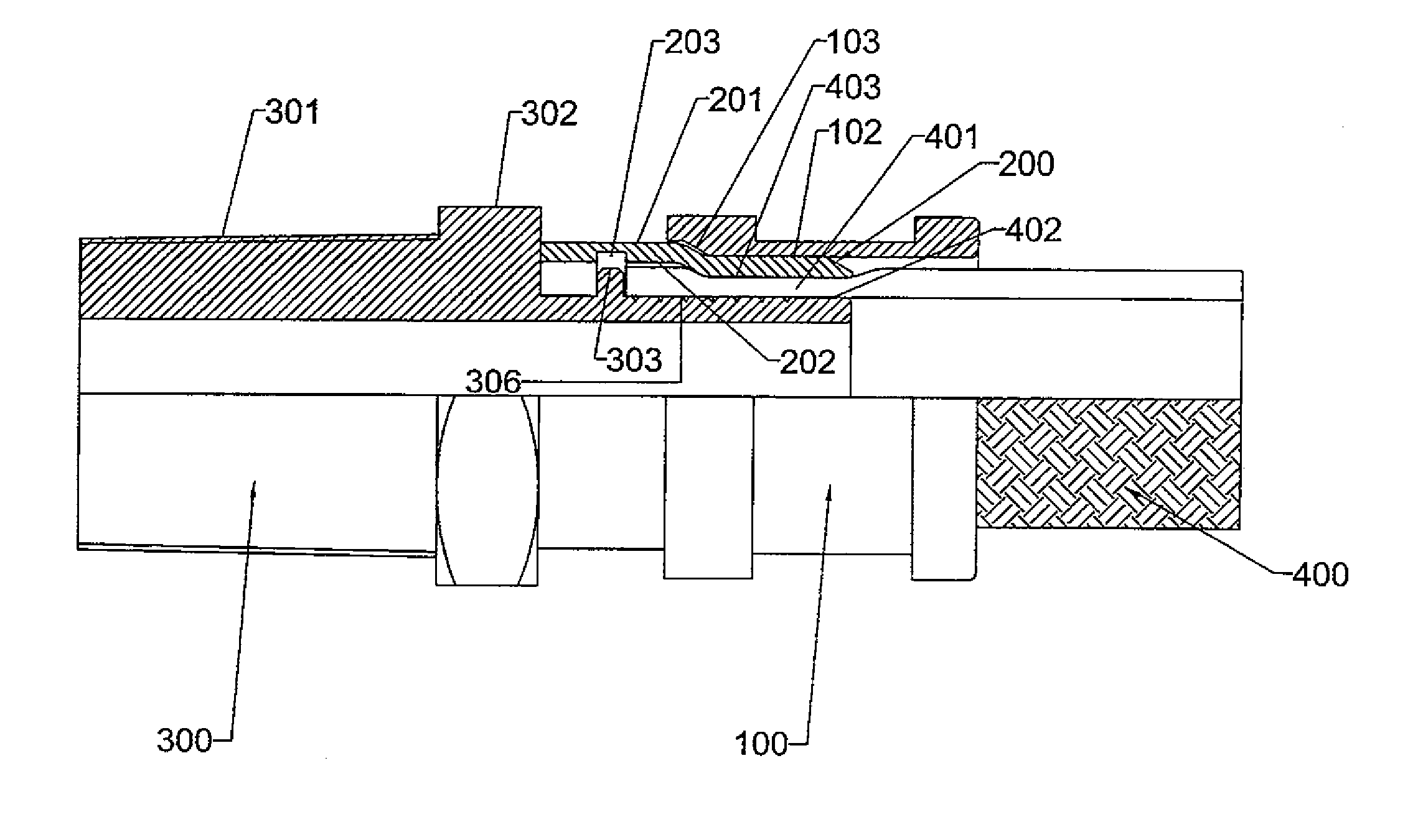
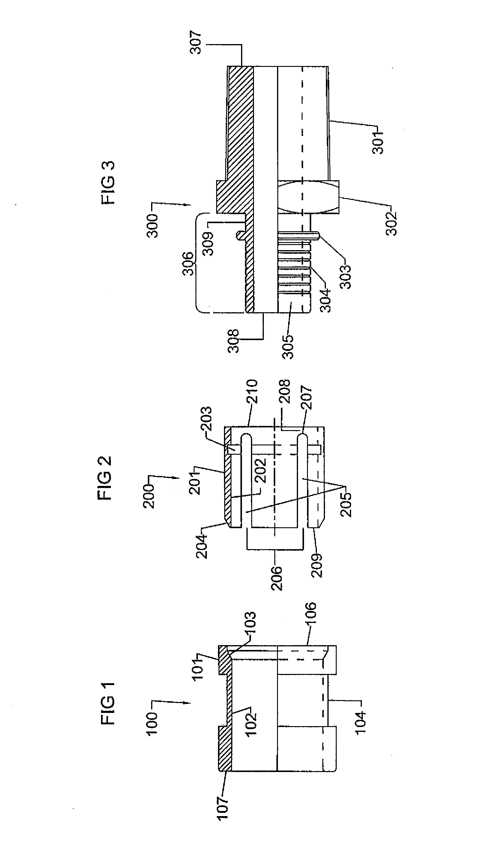
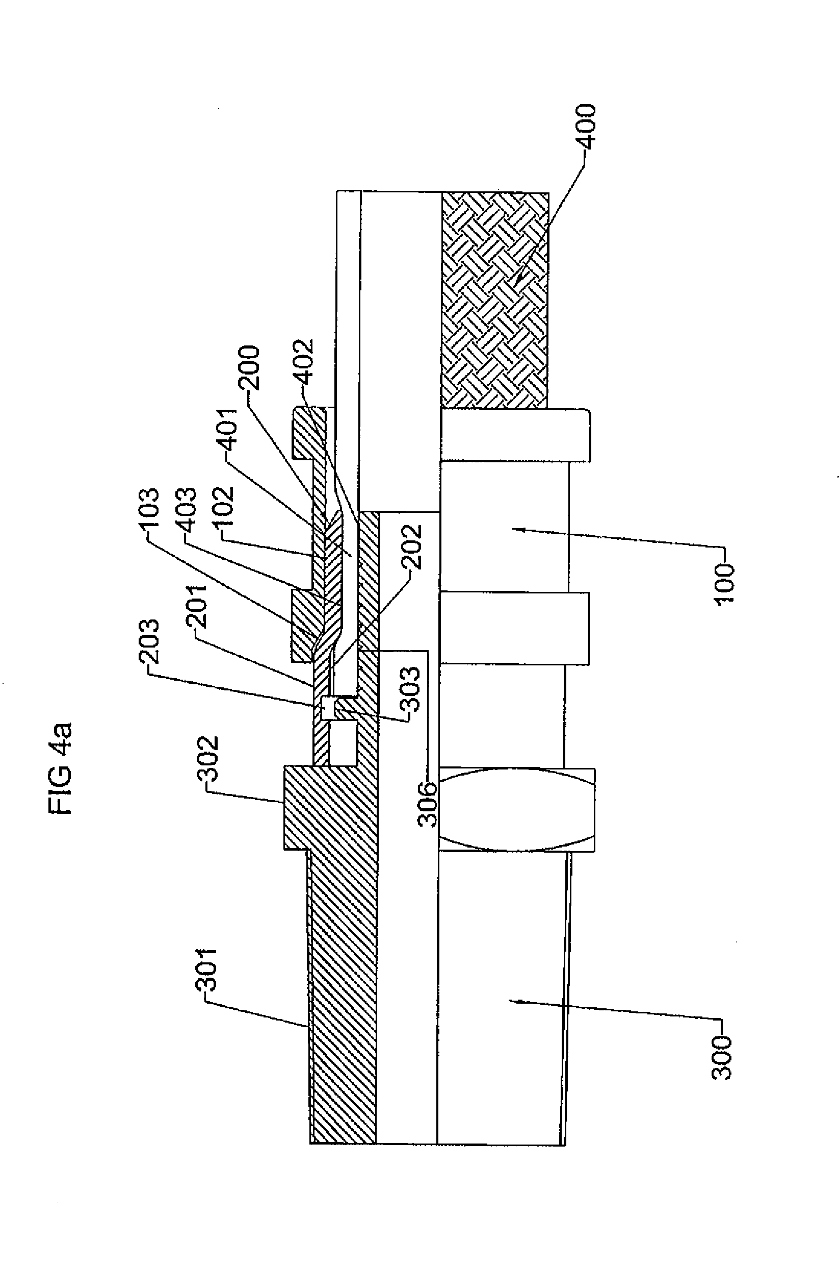
[0041]Referring to FIG. 1, a collar 100 comprises a substantially cylindrical like configuration having an outer surface 101 and an inner surface 102. Towards a second end 106 of collar 100 a tapered region 103 is provided on inner surface 102 such that the thickness of the collar wall decreases in the region of the taper 103 from the first end 107 to second end 106. Accordingly, the radius of the inner surface at the second end 106 is greater than the radius of the inner surface at the first end 107.

[0042]An annular groove 104 is recessed into outer surface 101 and positioned substantially midway between first and second ends 107, 106.

[0043]Referring to FIG. 2, an inner sleeve 200 comprises a substantial cylindrical configuration having an outer surface 201 and an inner surface 202. A leading edge 204 at a first end 209 comprises a taper extending between inner surface 202 and outer surface 201. Taper 204 corresponds in gradient to taper 103 provided at inner surface 102 of outer c...


PUM

PropertyMeasurementUnit
Forceaaaaaaaaaa
Radiusaaaaaaaaaa
Plasticityaaaaaaaaaa

Abstract

A hose end fitting in which a connection body (300) is secured to a hose end (401) by an inner sleeve (200) and an outer collar (100). A radius of an outer surface (201) of the inner sleeve (200) is greater than a radius of an inner surface (102) of the outer collar (100) such that when the outer collar (100) is forced over the inner sleeve (200), the inner sleeve is radially compressed onto the hose end. The outer collar (100) and inner sleeve (200) are locked in position by the radial expansion force of the compressed hose (401) and the inner sleeve (200).

Description

CROSS REFERENCE TO RELATED APPLICATION[0001]The subject patent application claims priority to and all the benefits of International Application No. PCT / GB20071003685, which was filed on Sep. 28, 2007 with the World Intellectual Property Organization.BACKGROUND OF THE INVENTION[0002]1. Field of the Invention[0003]The present invention relates to a hose fitting and in particular, although not exclusively, to a reusable hose fitting.[0004]2. Description of the Prior Art[0005]Rubber and plastic hoses find extensive use in a variety of specific industrial and domestic applications. In the majority of these applications a connection body is secured to at least one end of the hose so as to provide a means of connection to other hoses or devices.[0006]Generally, it is a requirement that these connection bodies, alternatively termed end fittings, are attached to the hose in such a way that fluid passing through the hose, typically under pressure or a partial vacuum, does not leak at the inte...

Claims


Application Information

Patent Timeline
IPC IPC(8): F16L33/22F16L33/207
CPCB25B27/10F16L33/225F16L33/2075
Inventor SETON-ANDERSON, RODERICK
Owner AFLEX HOSE
Learn More