Electronic apparatus, charger, charging system, and charging method

a technology of electric motors and charging systems, applied in the direction of transportation and packaging, d ac network circuit arrangements, etc., can solve the problems of reduced battery capacity and long charging time, and achieve the effect of reducing battery capacity, reducing charging time, and saving battery capacity

Active Publication Date: 2010-02-04
LENOVO INNOVATIONS LTD HONG KONG
View PDF3 Cites 4 Cited by
  • Summary
  • Abstract
  • Description
  • Claims
  • Application Information

AI Technical Summary

Benefits of technology

[0113]According to the present invention, in a condition that said electronic apparatus is removed from said charger, said battery-main circuit power supply switch is switched into ON by said switch control signal, so that an electric power is supplied from said battery to said main circuit, in a condition that said electronic apparatus is connected to said charger, not only said battery is started to be charged by said charger but also said main circuit is started to be supplied with said electric power from said charger, on the other hand, said battery-main circuit power supply switch is switched into OFF by said switch control signal, so that an electric power is stopped to be supplied from said battery to said main circuit.
[0114]Or else, in a condition that said electronic apparatus is removed from said charger, said battery-main circuit power supply switch is switched into ON by said switch control signal, so that an electric power is supplied from said battery to said main circuit, in a condition that said electronic apparatus is connected to said charger, not only said battery is started to be charged by said charger through said charging circuit but also said main circuit is started to be supplied with said electric power from said charger through said charging circuit, on the other hand, said battery-main circuit power supply switch is switched into OFF by said switch control signal, so that an electric power is stopped to be supplied from said battery to said main circuit.
[0115]Accordingly, in a condition that said electronic apparatus is connected to said charger, it is possible to prevent an electric power from being supplied from said battery to said main circuit. Therefore, a charging time can be shortened and a battery capacity can be saved. The battery-main circuit power supply switch can be switched automatically during the charge of the battery. Consequently, without a specific operation by the user, it is possible to avoid a problem that a capacity of the battery is reduced in spite of charging the battery, or that a time for charging the battery becomes long.
[0116]Further, when said user conducts said operation by said operation section in said connected condition of said charger and said electronic apparatus, said battery-main circuit power supply switch is switched into ON, so that an electric power is started to be supplied from said battery to said main circuit, and releasing of said connected condition of said charger and said electronic apparatus by said lock mechanism can be conducted only by a condition that said operation section is being operated. Therefore, in a condition that said electronic apparatus is removed from said charger, it is possible without fail that an electric power is started to be supplied from said battery to said main circuit. As a result, the power supply to the main circuit is never temporarily broken.
[0117]Furthermore, until a predetermined delay time has passed after said electronic apparatus was connected to said charger, a power supply from said battery to said main circuit is maintained in a condition that said battery-main circuit power supply switch is ON, when said predetermined delay time has passed after said electronic apparatus was connected to said charger, said battery-main circuit power supply switch is switched into OFF, so that said power supply from said battery to said main circuit is stopped. When the electronic apparatus is connected to said charger, it is possible that the power supply to the main circuit is never temporarily broken.

Problems solved by technology

This causes a problem that a capacity of the battery is reduced in spite of charging the battery, or that a time for charging the battery becomes long.

Method used


Image

  • Electronic apparatus, charger, charging system, and charging method
  • Electronic apparatus, charger, charging system, and charging method
  • Electronic apparatus, charger, charging system, and charging method

Examples


first embodiment

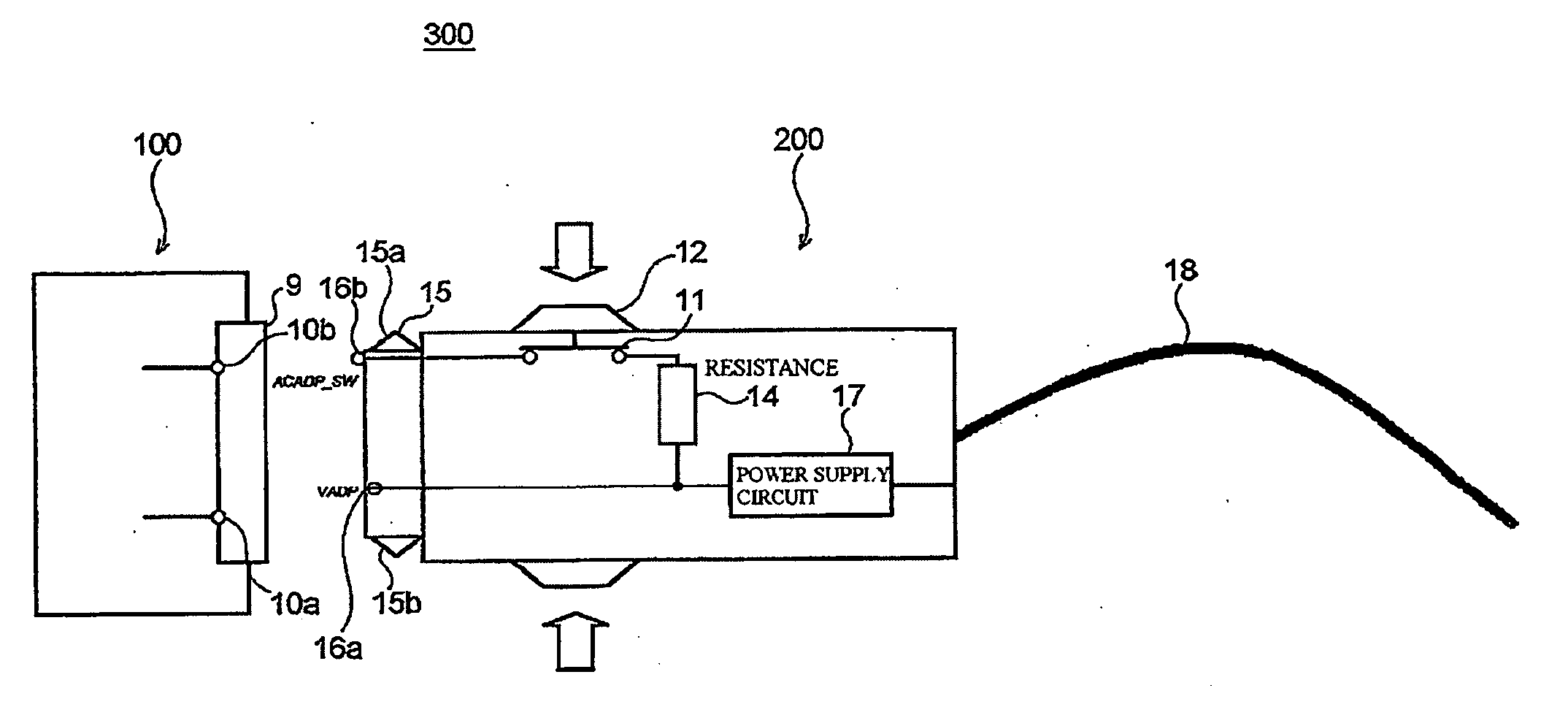
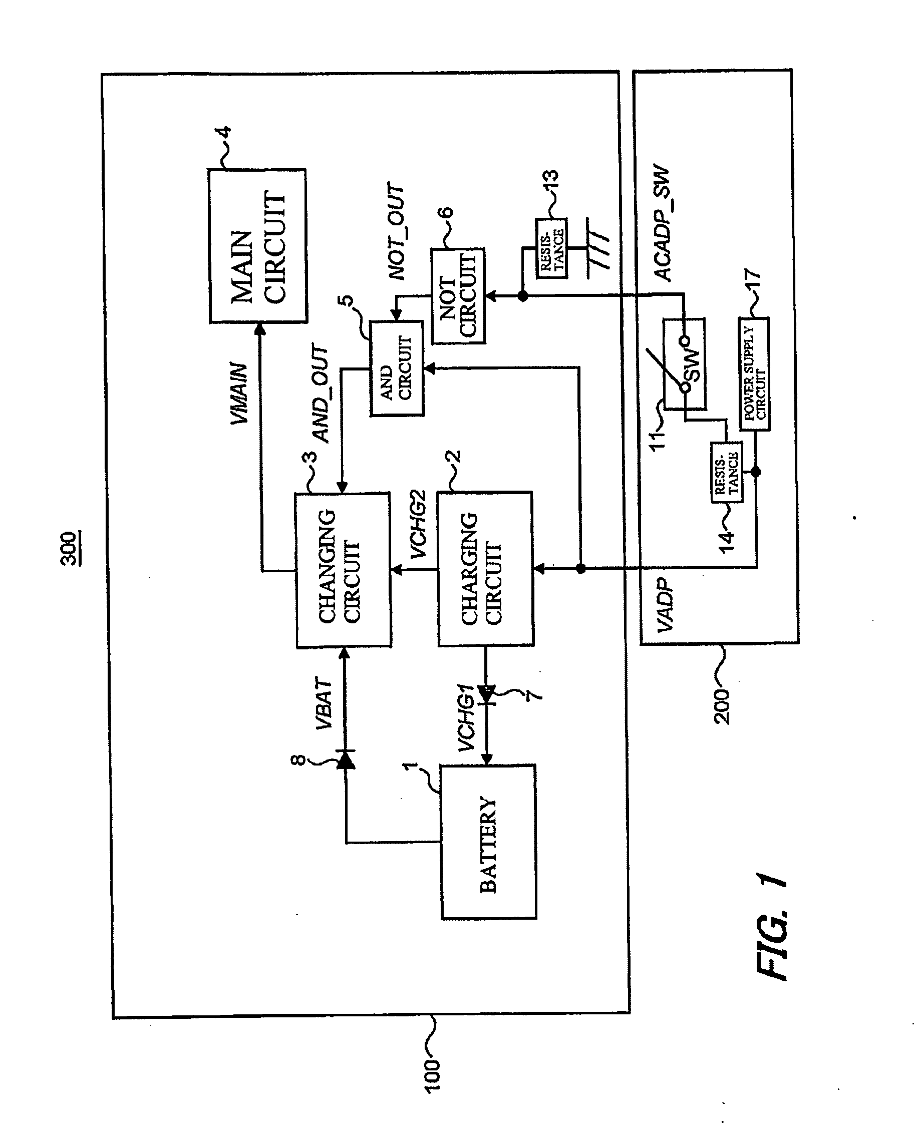
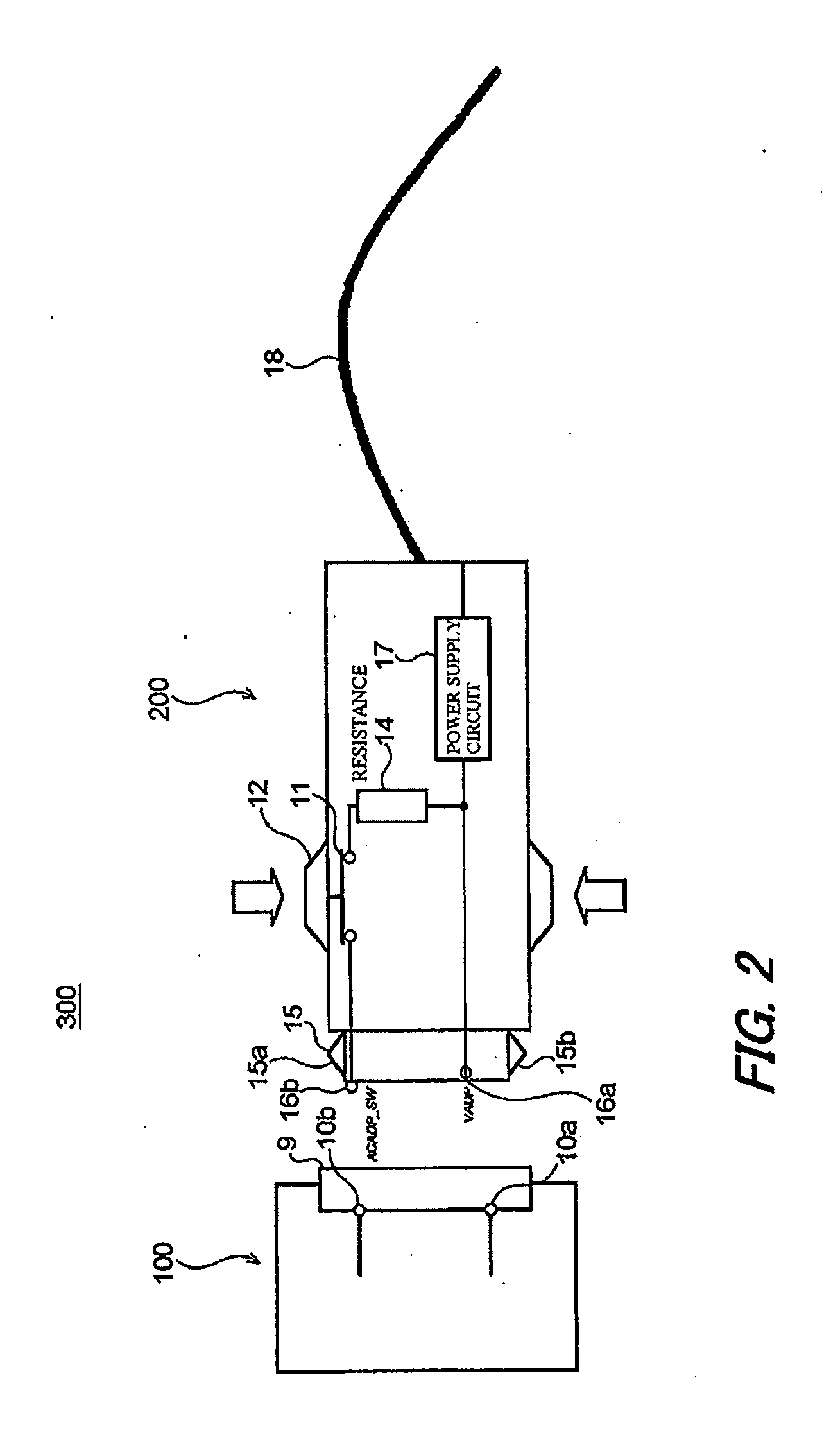
[0149]FIG. 1 is a view for showing a constitution of a charging system 300 according to a first embodiment of the present invention. FIG. 2 is a schematic view for showing the constitution of the charging system 300. FIG. 3 is a view for showing a constitution of a changing circuit 3 provided in a portable telephone (an electronic apparatus, a portable-type communication terminal apparatus) 100.

[0150]As illustrated in FIGS. 1 and 2, the charging system 300 according to the first embodiment of the present invention comprises the portable telephone 100, and an AC adapter 200 to which the portable telephone 100 is connected in a case of charging a battery 1 of the portable telephone 100.

[0151]As illustrated in FIG. 1, the portable telephone 100 comprises the battery 1 which is provided to be attachable to the portable telephone 100 and removable from the portable telephone 100, which is capable of being charged, and which functions as a power supply of the portable telephone 100, a cha...

second embodiment

[0251]FIG. 5 is a view for showing a constitution of a charging system 300 according to the second embodiment of the present invention. FIG. 6 is a view for showing a constitution of a changing circuit 3 provided in the charging system 300 according to the second embodiment of the present invention.

[0252]The second embodiment is different from the above-described first embodiment only in points that, as illustrated in FIG. 5, the second embodiment has a current detecting circuit 33 for detecting an amount of current of the VCHG1 in a supply route of the VCHG1, that, as illustrated in FIG. 6, the second embodiment has a switch 32 for rendering supply of the VCHG2 to the main circuit 4 to be stopped in a supply route of the VCHG2, and that a CPU (switch control means) 31 illustrated in FIG. 5 is capable of carrying out ON / OFF control of the switch 32 and the switch 21.

[0253]The CPU 31 totally controls operations of the portable telephone 10, and is included in the main circuit 4.

[0254...


PUM


Abstract

An electronic apparatus 100 has a main circuit 4 operable by a power supply from a battery 1, and a switch 21 for changing ON/OFF of the power supply from the battery 1 to the main circuit 4. A switch control signal is produced to switch ON/OFF of the switch 21 responsive to whether or not the electronic apparatus 100 is connected to the charger 200. If the electronic apparatus 100 is removed from the charger 200, the switch 21 becomes ON. The power is supplied from the battery 1 to the main circuit 4. The electronic apparatus 100 is connected to the charger 200, the charge of the battery 1 and the power supply from the charger 200 to the main circuit 4 is started. The switch 21 is OFF by the switch control signal. The power supply from the battery 1 to the main circuit 4 is stopped.

Description

TECHNICAL FIELD[0001]The present invention relates to an electronic apparatus which needs an electric charge, a charger, a charging system, and a charging method thereof.BACKGROUND TECHNIQUE[0002]Conventionally, while a battery of an electronic apparatus, such as a portable telephone, or the like is being charged, various circuits operable by being supplied with electric power from the battery (Hereunder, called main circuits) are charged by the battery.[0003]This causes a problem that a capacity of the battery is reduced in spite of charging the battery, or that a time for charging the battery becomes long.[0004]A technique disclosed, for example, in Patent Reference 1 is involved in conventional techniques made in view of the problems thus mentioned.[0005]Patent Reference 1 discloses a calling apparatus in which a battery is supplied with a charging power from a charger, the calling apparatus comprising: an electric power supplying terminal for directly supplying a main circuit wi...

Claims


Application Information

Patent Timeline
Patent Type & Authority Applications(United States)
IPC IPC(8): H02J3/00H02J7/00
CPCH02J7/0068H02J7/0044
Inventor OGURI, SHINJI
Owner LENOVO INNOVATIONS LTD HONG KONG
Why Eureka
Try Eureka