Voltage regulator with ripple compensation

a voltage regulator and ripple compensation technology, applied in the direction of instruments, dc-dc conversion, power conversion systems, etc., can solve the problems of headroom problem, nmos voltage regulators may no longer be able to properly regulate the output voltage on the output node vreg, and increase the cost of nmos voltage regulators. to achieve the effect of reducing voltage fluctuations

Active Publication Date: 2010-02-04
SYNOPSYS INC
View PDF10 Cites 16 Cited by
  • Summary
  • Abstract
  • Description
  • Claims
  • Application Information

AI Technical Summary

Benefits of technology

[0019]Embodiments of the present invention provide an electronic device. The electronic device includes at least one circuit coupled to an output node, wherein the output node is configured to provide power supply for the circuit at a predetermined voltage. The electronic device also includes a driving mechanism coupled to the output node, wherein driving mechanism 300 is configured to provide current to the output node to sustain the predetermined voltage on the output node. In addition, the electronic device includes boost circuit 308 coupled to the output node, wherein boost circuit 308 is configured to drive an additional current onto the output node to reduce fluctuations in a voltage of the output node when a load requires a transient switching current on the output node that is faster than the loop response time of driving mechanism 300.

Problems solved by technology

Unfortunately, as the output voltages required for these circuits are remaining approximately constant, the supply voltages available to the voltage regulators are being scaled downward much more aggressively.
This issue is generally referred to as a headroom problem.
Consequently, as supply voltages shrink, NMOS voltage regulators may no longer be able to properly regulate the output voltage on the output node VREG.
However, PMOS voltage regulators have a high output impedance beyond the operational amplifier's bandwidth, which can cause a “ripple” in the output voltage on the output node VREG when the voltage regulator is used in high-speed transient switching circuits.
Unfortunately, adding capacitance to the output node has drawbacks, such as requiring additional area and creating stability problems.

Method used


Image

  • Voltage regulator with ripple compensation
  • Voltage regulator with ripple compensation
  • Voltage regulator with ripple compensation

Examples


Embodiment Construction

[0031]The following description is presented to enable any person skilled in the art to make and use the invention, and is provided in the context of a particular application and its requirements. Various modifications to the disclosed embodiments will be readily apparent to those skilled in the art, and the general principles defined herein may be applied to other embodiments and applications without departing from the spirit and scope of the present invention. Thus, the present invention is not limited to the embodiments shown, but is to be accorded the widest scope consistent with the principles and features disclosed herein.

Electronic Device

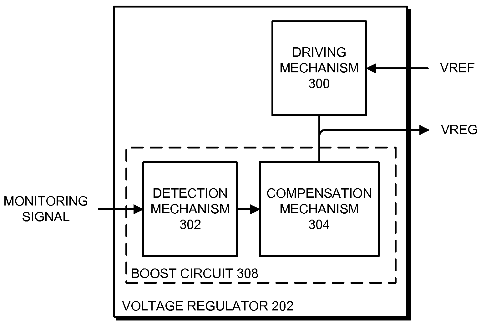
[0032]FIG. 2 presents an electronic device 200 in accordance with embodiments of the present invention. Generally, electronic device 200 can be any device that includes electrical circuits. For example, electronic device 200 can include, but is not limited to, a computer, a cellular phone, a controller, a hybrid device (i.e., a “smart phone”)...


PUM


Abstract

Embodiments of the present invention provide a voltage regulator. The voltage regulator includes a driving mechanism coupled to an output node (VREG), wherein the driving mechanism is configured to provide current to the output node to sustain a predetermined voltage on the output node. In addition, the voltage regulator includes a boost circuit coupled to the output node, wherein the boost circuit is configured to drive an additional current onto the output node to reduce fluctuations in the output node voltage when a load coupled to the output node requires a transient switching current that is faster than the loop response time of the driving mechanism. Furthermore, the boost circuit is biased using a self-tracking mechanism to provide accurate duration and level of the current to the output node in a transient switching event.

Description

BACKGROUND[0001]1. Field of the Invention[0002]Embodiments of the present invention generally relate to the design of voltage regulators. More specifically, embodiments of the present invention provide a low-voltage regulator with ripple compensation.[0003]2. Related Art[0004]Modern high-speed circuits are increasingly requiring voltage regulators that can generate a stable output voltage using low supply voltages. For example, universal serial bus (USB) circuits, peripheral component interface express (PCIe) circuits, and other such high-speed circuits can require output voltages of 1.2 V to be generated from supply voltages of 1.8 V or lower. Unfortunately, as the output voltages required for these circuits are remaining approximately constant, the supply voltages available to the voltage regulators are being scaled downward much more aggressively. Because the difference between the output voltages required to be output by the regulator and the supply voltages that are provided to...

Claims


Application Information

Patent Timeline
Patent Type & Authority Applications(United States)
IPC IPC(8): G05F1/56
CPCH02M3/158H02M3/156
Inventor LAM, NELSON S. H.TOFFOLON, DINO A.
Owner SYNOPSYS INC
Why Eureka
Try Eureka