Biometrics authentication system

a biometric authentication and biometric technology, applied in the field of biometric authentication system, can solve the problems of complicated and large apparatus configuration, difficult to apply them to a small apparatus such as a cellular phone, and difficult to configure or arrange illumination means, etc., and achieve the effect of simple configuration

Inactive Publication Date: 2010-02-04
SONY CORP
View PDF9 Cites 130 Cited by
  • Summary
  • Abstract
  • Description
  • Claims
  • Application Information

AI Technical Summary

Benefits of technology

[0008]It is desirable to provide a biometrics authentication system having a small and simple configuration and being capable of implementing both of authentication of a living body and position detection of an object.
[0011]In the biometrics authentication system according to the embodiment of the invention, light applied from the light source to the object is condensed by the microlens array section, and then is detected by the light-sensing device, thereby the light detection data is obtained. On the basis of the light detection data, authentication of the living body by the authentication section and position detection of the object by the position detection section are performed, so it is not necessary to separately arrange various position sensors. Therefore, the biometrics authentication system with a small and simple configuration may implement both of biometrics authentication and position detection.

Problems solved by technology

However, when both of the touch panel and the biometrics authentication system are mounted in one apparatus, the whole configuration of the apparatus is complicated and large, and in particular, it is difficult to apply them to a small apparatus such as a cellular phone.
Moreover, it is difficult to configure or arrange an illumination means so as to be used for both of the touch panel and the biometrics authentication system.

Method used


Image

  • Biometrics authentication system
  • Biometrics authentication system
  • Biometrics authentication system

Examples


first embodiment

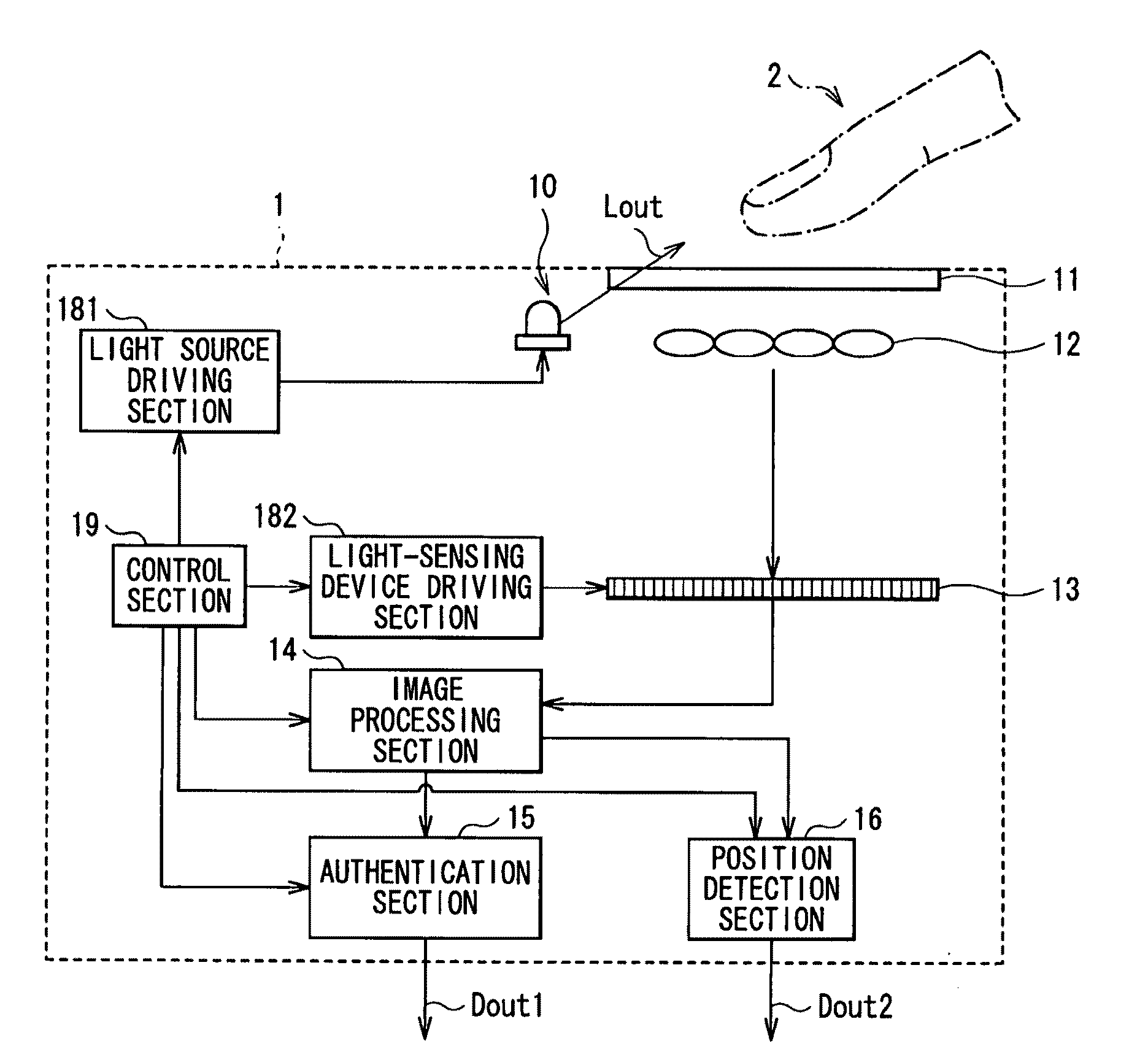
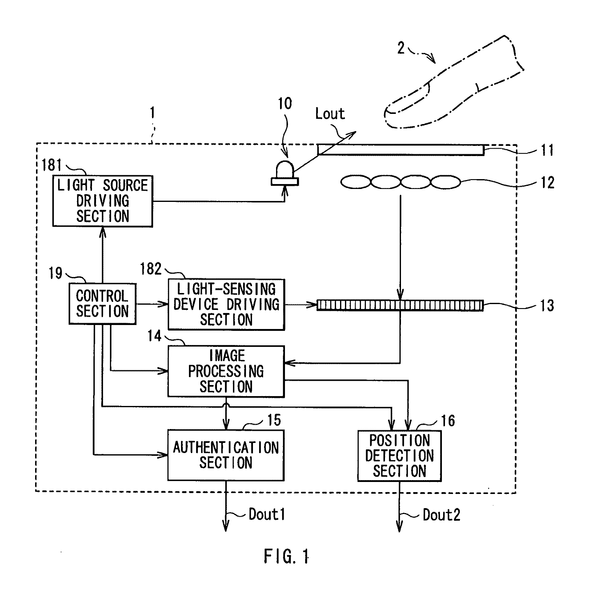
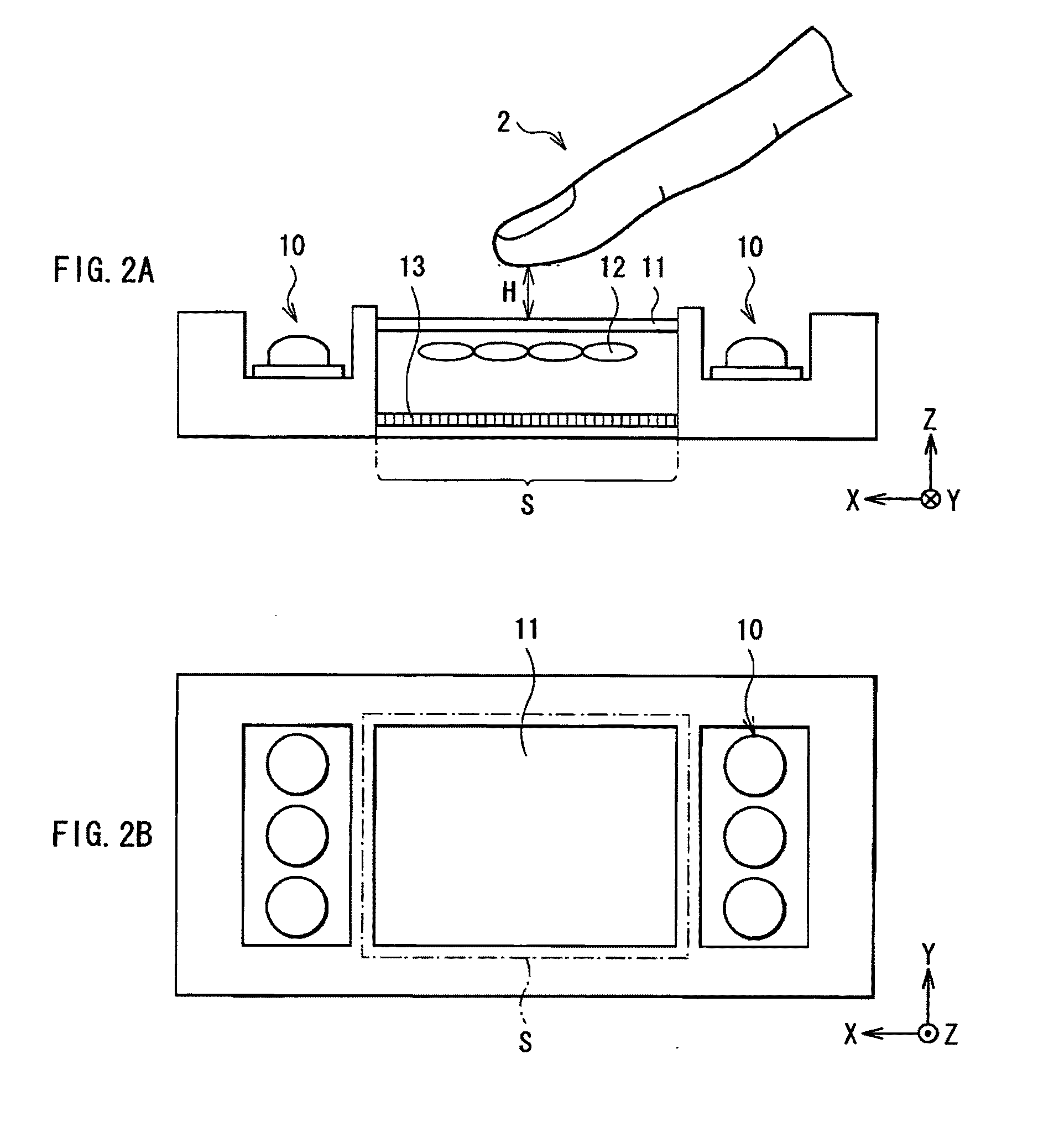
[0036]FIG. 1 illustrates the whole configuration of a biometrics authentication system (a biometrics authentication system 1) according to a first embodiment of the invention. FIG. 2A is a schematic sectional view of the configuration of a main part of the biometrics authentication system 1, and FIG. 2B is a schematic view of the biometrics authentication system 1 viewed from above. The biometrics authentication system 1 outputs authentication result data Dout1 of a living body (for example, a fingertip) 2 as an object subjected to image pickup, and outputs position data Dout2 of the living body 2. The biometrics authentication system 1 includes a near-infrared light source 10, a cover glass 11, a microlens array 12, a light-sensing device 13, an image processing section 14, an authentication section 15, a position detection section 16, a light source driving section 181, a light-sensing device driving section 182 and a control section 19.

[0037]The near-infrared light source 10 is a...

modification 1

[0060]FIG. 7 is a schematic sectional view of the configuration of a main part of a biometrics authentication system according to Modification 1 of the first embodiment. The biometrics authentication system according to the modification has the same configuration as that of the biometrics authentication system 1 according to the first embodiment except for the configurations of the light source and the light-sensing device. Therefore, like components are denoted by like numerals as of the biometrics authentication system 1 and will not be further described.

[0061]In the modification, a light-sensing device 25 and a backlight 24 are arranged below the microlens array 12. The backlight 24 is a light source emitting near-infrared light and light in a visible region (hereinafter simply referred to as visible light), for example, white light, and includes, for example, a plurality of CCFLs (Cold Cathode Fluorescent Lamps) or LEDs arranged. The light-sensing device 25 is arranged on the fo...

modification 2

[0065]FIG. 8 is a schematic sectional view of the configuration of a main part of a biometrics authentication system according to Modification 2 of the first embodiment. The biometrics authentication system according to the modification has the same configuration as those of the first embodiment and Modification 1, except that both of the near-infrared light sources 10 used in the first embodiment and the backlight 24 used in Modification 1 are arranged. However, the near-infrared light sources 10 function as light sources for biometrics authentication, and the backlight 24 functions as a light source for position detection.

[0066]Thereby, in biometrics authentication, near-infrared light from the near-infrared light sources 10 is used to produce light detection data for authentication, and in position detection, light from the backlight 24 is used to produce light detection data for position detection. The light detection data for biometrics authentication or position detection prod...


PUM


Abstract

A biometrics authentication system having a small and simple configuration and being capable of implementing both of biometrics authentication and position detection is provided. A biometrics authentication system includes: a light source emitting light to an object; a microlens array section condensing light from the object; a light-sensing device obtaining light detection data of the object on the basis of the light condensed by the microlens array section; a position detection section detecting the position of the object on the basis of the light detection data obtained in the light-sensing device; and an authentication section, in the case where the object is a living body, performing authentication of the living body on the basis of the light detection data obtained in the light-sensing device.

Description

BACKGROUND OF THE INVENTION[0001]1. Field of the Invention[0002]The present invention relates to a biometric authentication system using a light-sensing device.[0003]2. Description of the Related Art[0004]In related arts, image pickup apparatuses picking up an image of a structure in a living body part are used in biometrics authentication systems or the like. Typically, as such an image pickup apparatus has a large thickness, the image pickup apparatus is arranged outside an apparatus to which the image pickup apparatus is applied, or an optical system and a detection system are independently arranged as described in Japanese Unexamined Patent Application Publication Nos. 2005-312748 and 2006-181296. However, in recent years, according to a reduction in sizes or profiles of various apparatuses, constraints of manufacturability or design, or the like, a reduction in the size and profile of the above-described biometrics authentication system is desired, and it is desired to mount th...

Claims


Application Information

Patent Timeline
Patent Type & Authority Applications(United States)
IPC IPC(8): G05B19/00G06V10/141
CPCG06F21/32G06K9/00033G06K2209/05G06K9/2027G06K2009/00932G06K9/00885G06V40/1312G06V40/10G06V40/14G06V10/141G06V2201/03
Inventor YAMAMOTO, KENJISATO, HIDEOICHIMURA, ISAOWATANABE, TOSHIOKAI, SHINICHIKAJIHARA, JUNJIHAYASAKA, KENGO
Owner SONY CORP
Why Eureka
Try Eureka