Liquid ejecting head and liquid ejecting apparatus

a liquid ejecting head and liquid ejecting technology, which is applied in the direction of printing and inking apparatus, etc., can solve the problems of fixed plate rotation rate, difficult or disadvantageous to increase the density of nozzle arrays and nozzle lines with a single head body structure, and achieve enhanced print quality and high positional precision

Inactive Publication Date: 2010-02-04
SEIKO EPSON CORP
View PDF3 Cites 13 Cited by
  • Summary
  • Abstract
  • Description
  • Claims
  • Application Information

AI Technical Summary

Benefits of technology

[0009]An advantage of some aspects of the invention is to provide a liquid ejecting head that makes it possible to fix a plurality of head bodies, or a single head body, to a frame with high positional precision, thereby enhancing print quality. In addition, the invention further relates to, as an advantage of some aspects thereof, a liquid ejecting apparatus that is provided with such a liquid ejecting head.
[0011]With such a structure, in comparison with a case where the fixation plate is directly fixed to the frame by screwing a fixation screw through the fixation plate, it is possible to substantially reduce the risk of the positional misalignment of the head body with respect to the frame.
[0012]It is preferable that the liquid ejecting head according to the first aspect of the invention described above should further include a holding plate fixation screw and at least two washers, wherein the holding plate is fixed to the frame by means of the holding plate fixation screw; at least two washers mentioned above are provided between the holding plate and the holding plate fixation screw; and a coefficient of friction between one of the two washers and the other thereof is smaller than a coefficient of friction between the one washer and the holding plate, and in addition, is smaller than a coefficient of friction between the other washer and the holding plate fixation screw. With such a preferred structure, low-friction rotation occurs between the two washers at the time when the holding plate fixation screw is screwed for fixation. That is, the one of these two washers and the other thereof function as a kind of a buffer that absorbs and reduces a rotation force that acts at the time when the holding plate fixation screw is screwed for fixation, which means that the rotation force is substantially less likely to be transmitted to the holding plate. Therefore, it is possible to reduce the occurrence of the turning of the holding plate. Thus, it is possible to further reduce the risk of the positional misalignment of the head body with respect to the frame.
[0013]It is preferable that the liquid ejecting head having the preferred structure explained above should further include a fixation plate fixation screw, wherein the holding plate is fixed to the frame by means of the holding plate fixation screw; and the fixation plate is fixed to the frame by means of the fixation plate fixation screw. With such a preferred structure, since the fixation plate is fixed to the frame with the use of the fixation plate fixation screw, even in a case where the holding plate fixation screw has become loosened as time elapses because of a small coefficient of friction between the two washers, it is possible to prevent the fixation plate, which is fixed to the head body, from becoming unfastened from the frame. Furthermore, with such a preferred structure, it is possible to remove the head body from the frame easily just by loosening the fixation plate fixation screw(s) and the holding plate fixation screw(s).
[0015]Since a plurality of head bodies, or a single head body, is fixed to a frame with high positional precision, a liquid ejecting apparatus according to the second aspect of the invention described above achieves enhanced print quality.

Problems solved by technology

However, it is practically difficult or disadvantageous to increase the nozzle array density and the nozzle line with a single head body structure because the yield rate of a head body, that is, the yield rate of a head component, decreases and further because the production cost thereof increases.
However, if each head body is fixed to the frame by fastening screws through the fixation plates fixed to the head body and into the frame after the positional determination of the head body with respect to the frame with high precision, the rotation force of the screw that is applied at the time of fastening thereof causes the fixation plate to turn.
As a result of the turning of the fixation plate, a problem arises in that the position of the head body that has been determined with high precision becomes shifted, which means that misalignment in head position occurs.
That is, the same problem could occur in various kinds of other liquid ejecting heads that eject liquid other than ink.

Method used


Image

  • Liquid ejecting head and liquid ejecting apparatus
  • Liquid ejecting head and liquid ejecting apparatus
  • Liquid ejecting head and liquid ejecting apparatus

Examples


first embodiment

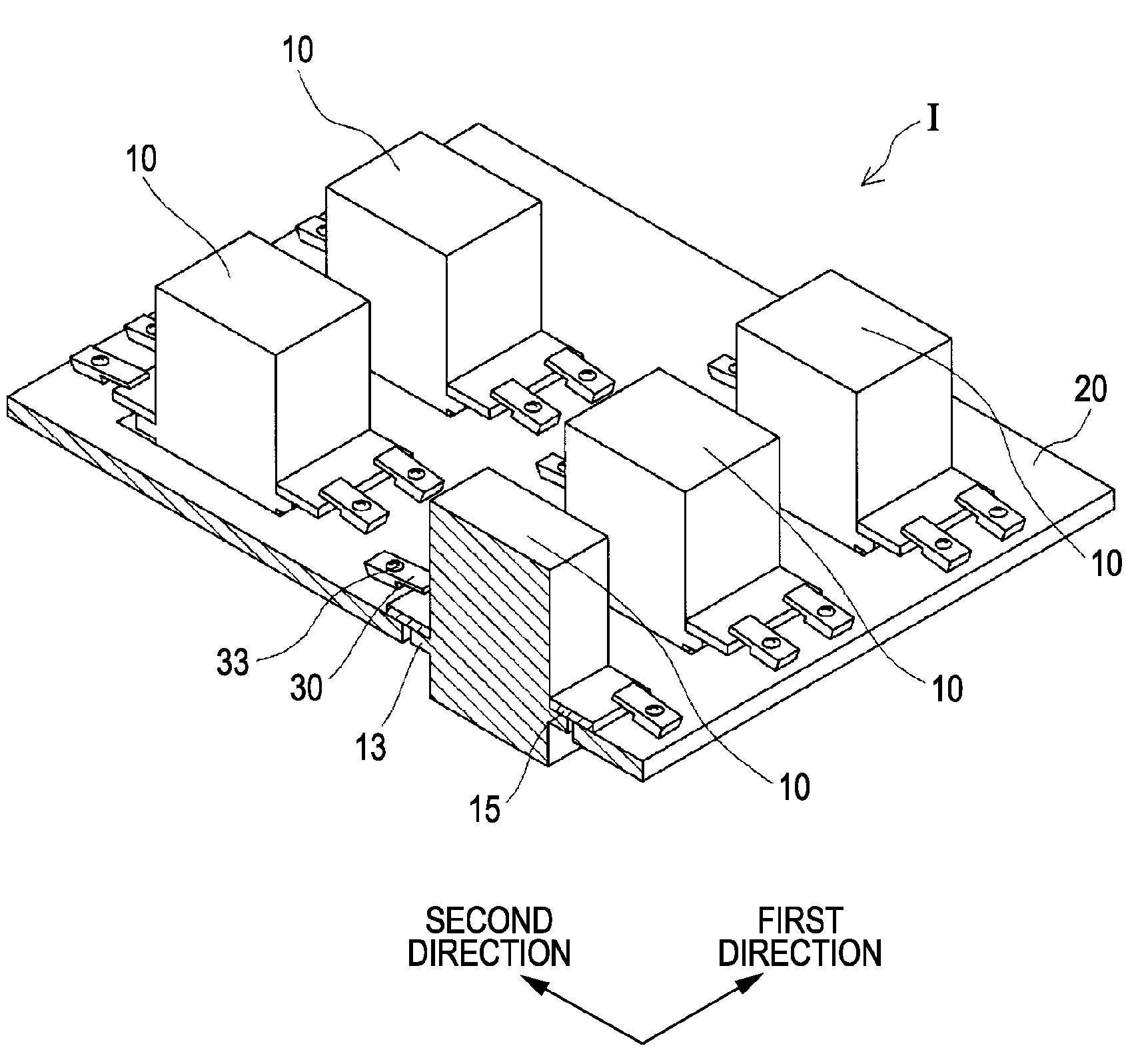
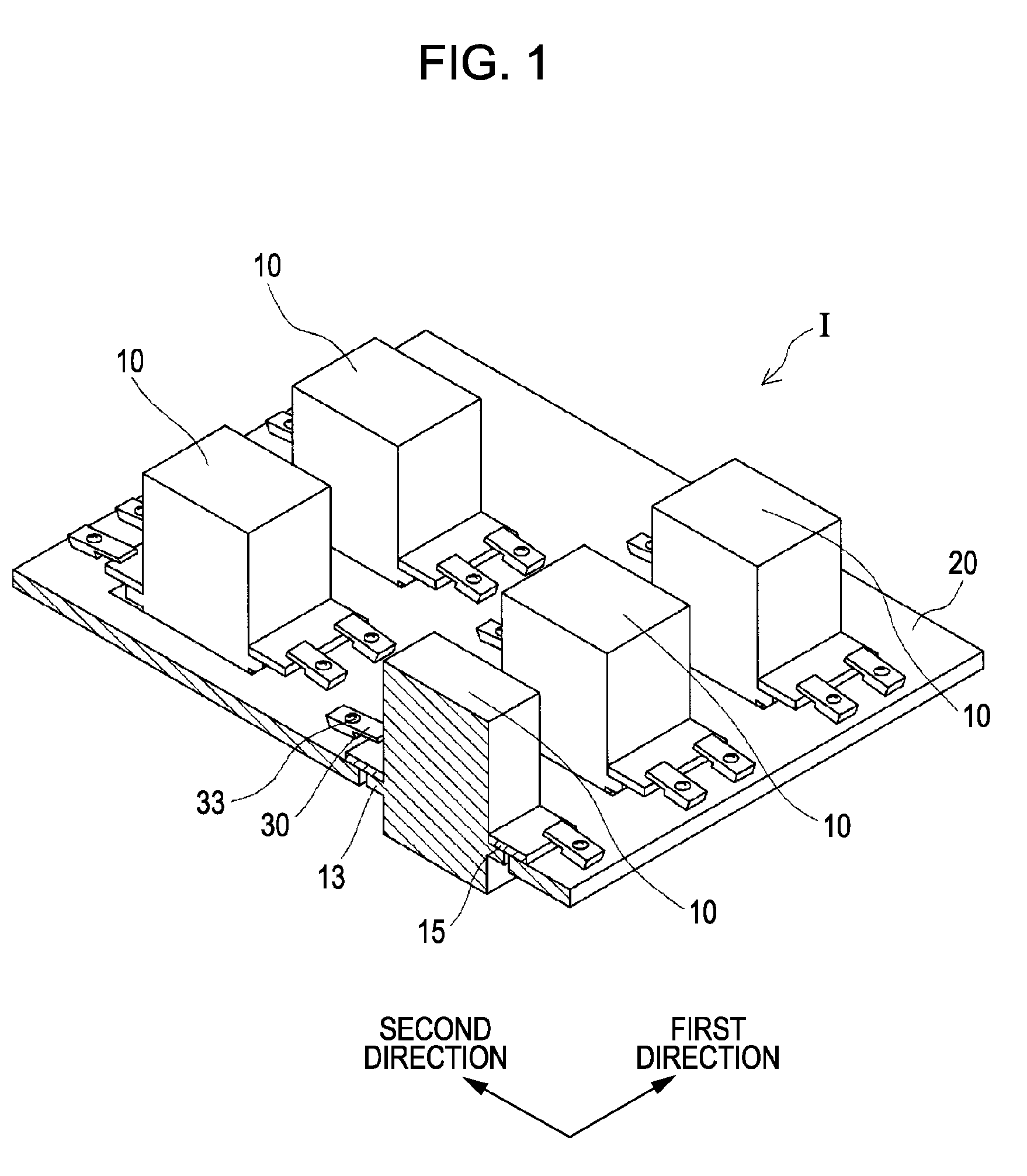
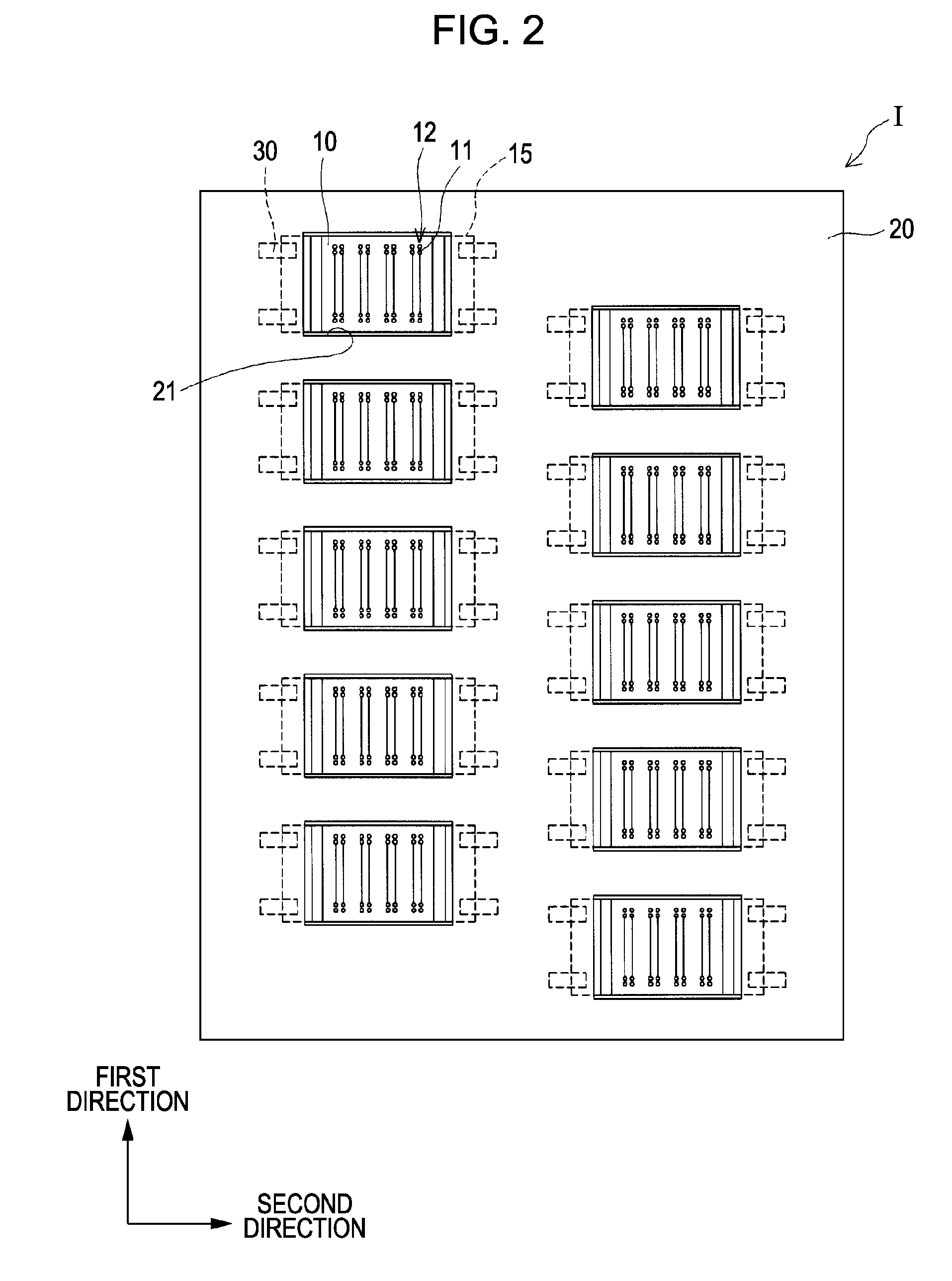
[0026]FIG. 1 is a perspective view that schematically illustrates an example of the configuration of an ink-jet recording head that is an example of various kinds of liquid ejecting heads according to a first embodiment of the invention. FIG. 2 is a plan view that schematically illustrates an example of the configuration of the ink-jet recording head that is viewed from the nozzle side thereof. FIG. 3A is a plan view that schematically illustrates an example of an essential part of the ink-jet recording head that is viewed from the other side that is opposite to the nozzle side thereof. FIG. 3B is a sectional view taken along the line IIIB-IIIB of FIG. 3A.

[0027]As illustrated in these drawings, an ink-jet recording head I according to the present embodiment of the invention is provided with a plurality of head “bodies”10 and a frame 20. The term “head bodies” means, for example, the head components of the ink-jet recording head I without any limitation thereto. After the positional ...

second embodiment

[0050]FIG. 4A is a sectional view that schematically illustrates an example of an essential part of an ink-jet recording head that is an example of various kinds of liquid ejecting heads according to a second embodiment of the invention. FIG. 4B is an enlarged sectional view that schematically illustrates an example of a screw-fastening structure of the ink-jet recording head illustrated in FIG. 4A. In the following description of an ink-jet recording head according to the second embodiment of the invention, the same reference numerals are consistently used for the same components as those of the ink-jet recording head according to the first embodiment of the invention so as to omit any redundant explanation or simplify explanation thereof.

[0051]In the configuration of the ink-jet recording head I according to the foregoing first embodiment of the invention, the holding plate 30 is fixed to the frame 20 by means of the holding plate fixation screw 33. Under the screw-fastening force...

third embodiment

[0058]FIG. 5 is a plan view that schematically illustrates an example of an essential part of an ink-jet recording head that is an example of various kinds of liquid ejecting heads according to a third embodiment of the invention. In the following description of an ink-jet recording head according to the third embodiment of the invention, the same reference numerals are consistently used for the same components as those of the ink-jet recording head according to the first embodiment of the invention or those of the ink-jet recording head according to the second embodiment of the invention so as to omit any redundant explanation or simplify explanation thereof.

[0059]As illustrated in FIG. 5, the ink-jet recording head I according to the third embodiment of the invention is provided with the two washers 34a and 34b provided between the holding plate 30 and the screw head of the holding plate fixation screw 33, which is the same structure as that of the ink-jet recording head I accordi...


PUM


Abstract

A liquid ejecting head includes: a head body that includes a plurality of nozzles and ejects liquid drops from the nozzles; a frame that supports the head body; a fixation plate by means of which the head body is fixed to the frame; and a holding plate that applies holding pressure to the fixation plate toward the frame so that the fixation plate is fixed to the frame.

Description

BACKGROUND[0001]1. Technical Field[0002]The present invention relates to a liquid ejecting head that includes at least one head body that ejects liquid drops from nozzles thereof and a frame that supports the head body, which is fixed to the frame by means of at least one fixation plate. The invention further relates to a liquid ejecting apparatus that is provided with such a liquid ejecting head.[0003]2. Related Art[0004]A liquid ejecting apparatus is provided with a liquid ejecting head that is capable of ejecting liquid in the form of liquid drops. As a typical example of a liquid ejecting apparatus, an ink-jet recording apparatus such as an ink-jet printer, an ink-jet plotter, and the like ejects ink that is supplied from ink containers such as ink cartridges, ink tanks, or the like.[0005]There is a demand for such a liquid ejecting head used in a liquid ejecting apparatus that has a high nozzle array density and a long nozzle line. However, it is practically difficult or disadv...

Claims


Application Information

Patent Timeline
Patent Type & Authority Applications(United States)
IPC IPC(8): B41J2/145
CPCB41J2/145B41J2202/20B41J2202/19
Inventor KOBAYASHI, YOSHIHIROKAWAMOTO, MAKOTOMITSUHASHI, MASATO
Owner SEIKO EPSON CORP
Why Eureka
Try Eureka