Optical Coherence Tomographic Imaging Method and Optical Coherence Tomographic Imaging Apparatus

Inactive Publication Date: 2010-02-04
CANON KK
View PDF3 Cites 11 Cited by
  • Summary
  • Abstract
  • Description
  • Claims
  • Application Information

AI Technical Summary

Benefits of technology

[0027]According to the present invention, in a Fourier domain optical coherence tomographic imaging apparatus, it is possible to obtain, from a wavelength spectr

Problems solved by technology

Such a scheme not only takes time for measurements but also

Method used


Image

  • Optical Coherence Tomographic Imaging Method and Optical Coherence Tomographic Imaging Apparatus
  • Optical Coherence Tomographic Imaging Method and Optical Coherence Tomographic Imaging Apparatus
  • Optical Coherence Tomographic Imaging Method and Optical Coherence Tomographic Imaging Apparatus

Examples


first embodiment

[0036]In a first embodiment of the present invention, reference will be made to an optical coherence tomographic imaging apparatus (hereinafter also referred to as an OCT apparatus) to which the present invention is applied, while using the accompanying drawings.

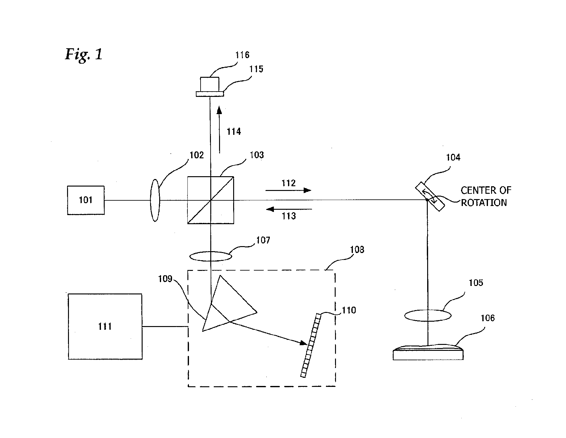
[0037]First of all, the construction of the OCT apparatus will be roughly described while referring to FIG. 1. The light emitted from a light source 101 is divided into measurement light 112 and reference light 114 by means of a beam splitter 103 through a lens 102. The measurement light 112 reaches an object 106 to be inspected through an XY scanner 104 and an object lens 105. A transparent film is formed on the object 106 to be inspected. Return light 113 scattered and reflected on a surface and an interface thereof returns while passing through the object lens 105, the XY scanner 104, and the beam splitter 103 in this order. In addition, the return light further reaches a spectroscope 108 arranged at a detection position ...

second embodiment

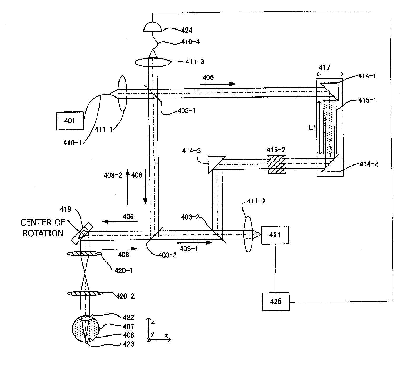
[0058]In a second embodiment of the present invention, reference will be made to an optical system in an ophthalmic optical coherence apparatus to which the present invention is applied, by using FIG. 4.

[0059]FIG. 4 illustrates constructing a Mach-Zehnder interference system as a whole. The light emitted from a light source 401 is guided to a lens 411-1 through a single-mode fiber 410-1. Further, the light is divided into reference light 405 and measurement light 406 by means of a beam splitter 403-1. The measurement light 406 is returned as return light 408 through reflection or scattering by means of an eye 407 which is an object to be inspected, after which the return light is combined with the reference light405 by means of a beam splitter 403-2 to enter a spectroscope 421. Here, the light source 401 is an SLD (Super Luminescent Diode) which is a typical low-coherence light source. In view of the fact, that the eye is measured, near-infrared light is suitable for the wavelength ...


PUM


Abstract

An optical tomographic diagnostic apparatus is characterized by executing a first step (S1) to acquire a wavelength spectrum, a second step (S2) to increase the number of elements of the wavelength spectrum, a third step (S3 and S4) to convert the wavelength spectrum into a wavenumber spectrum and to decrease the number of elements to provide a wavenumber spectrum of equal intervals, and a fourth step (S5) to acquire tomographic information of the object to be inspected from the wavenumber spectrum. As a result, a wavenumber spectrum of equal intervals can be obtained which is faithful to a physical phenomenon, and more accurate tomographic information can be obtained.

Description

BACKGROUND OF THE INVENTION[0001]1. Field of the Invention[0002]The present invention relates to an optical coherence tomographic imaging apparatus, and in particular, to an optical coherence tomographic imaging apparatus having a coherent optical system used for medical application.[0003]2. Description of the Related Art[0004]Today, a variety of ophthalmic equipment using optical instruments is used. These are, for example, an anterior camera, a fundus camera, a confocal scanning laser ophthalmoscope (Scanning Laser Ophthalmoscope: SLO), etc. In particular, an optical coherence tomographic imaging apparatus (hereinafter referred to as an OCT apparatus) is to obtain a tomographic image of an object to be inspected at high resolution, and is now becoming a necessary and indispensable apparatus in specialty outpatient clinics for retina care.[0005]The above-mentioned OCT apparatus uses low-coherence light as a light source. The light from the light source is divided into measurement l...

Claims


Application Information

Patent Timeline
IPC IPC(8): G01B9/02
CPCG01N21/4795G01B9/02083G01B9/02091G01B9/02044
Inventor SUEHIRA, NOBUHITO
Owner CANON KK
Why Eureka
Try Eureka