X-ray image diagnosis apparatus and control method

a control technique and image technology, applied in the field of control techniques of x-ray image diagnosis apparatuses, can solve the problems of deteriorating operation efficiency, delay in action, and excessive exposure of objects to be examined to x-rays, so as to avoid the risk of excessive exposure of objects

Inactive Publication Date: 2010-02-04
CANON KK
View PDF13 Cites 17 Cited by
  • Summary
  • Abstract
  • Description
  • Claims
  • Application Information

AI Technical Summary

Benefits of technology

[0017]According to the present invention, the X-ray image diagnosis apparatus capable of accepting control operations from a plurality of operation panels can ensure convenience for operators while avoiding the risk of excessively exposing an object to X-rays.

Problems solved by technology

That is, there is a risk that an object to be examined may be excessively exposed to X-rays.
This will lead to deterioration in operation efficiency and a delay in taking action in an emergency.

Method used


Image

  • X-ray image diagnosis apparatus and control method
  • X-ray image diagnosis apparatus and control method
  • X-ray image diagnosis apparatus and control method

Examples


first embodiment

[0029]

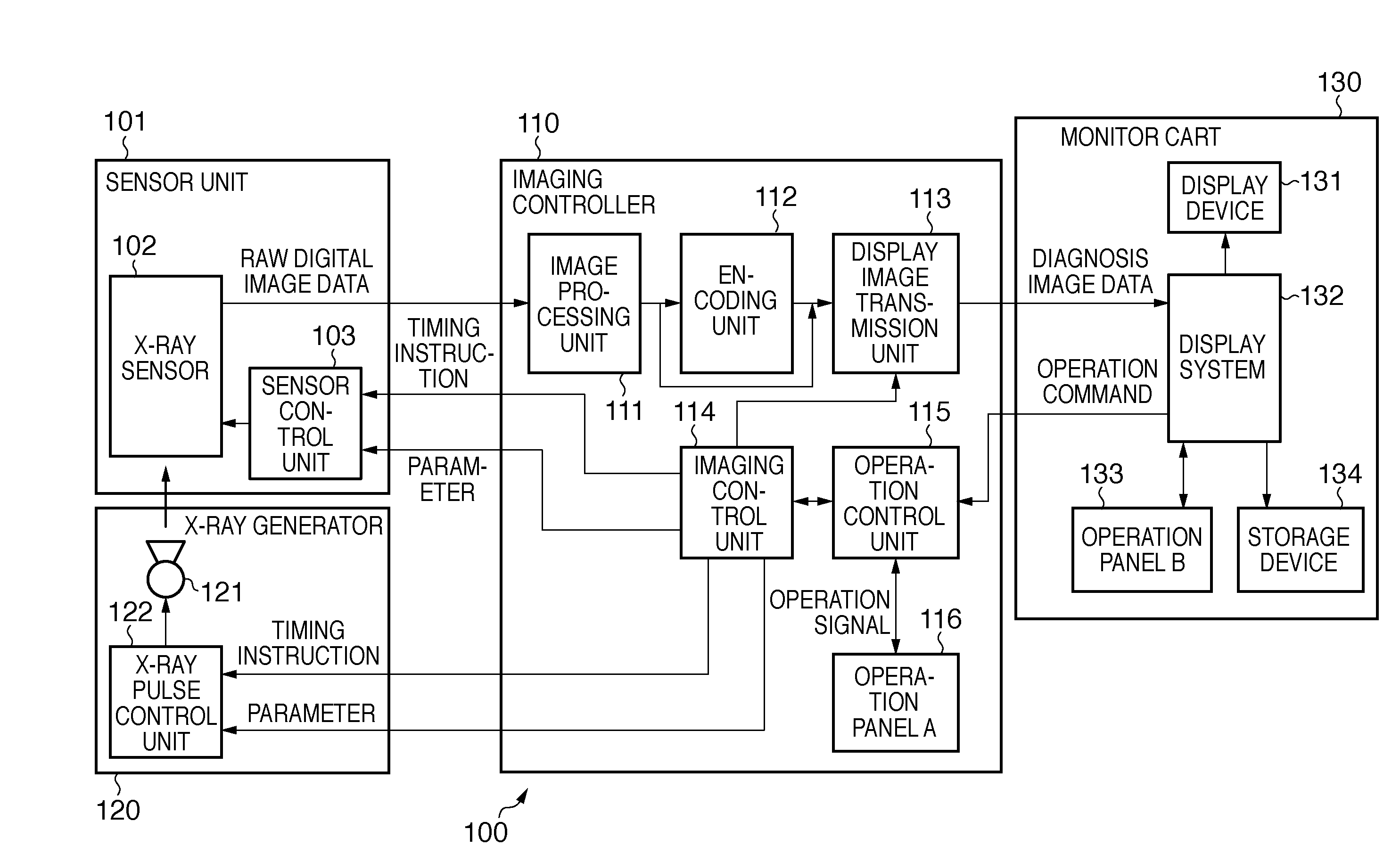
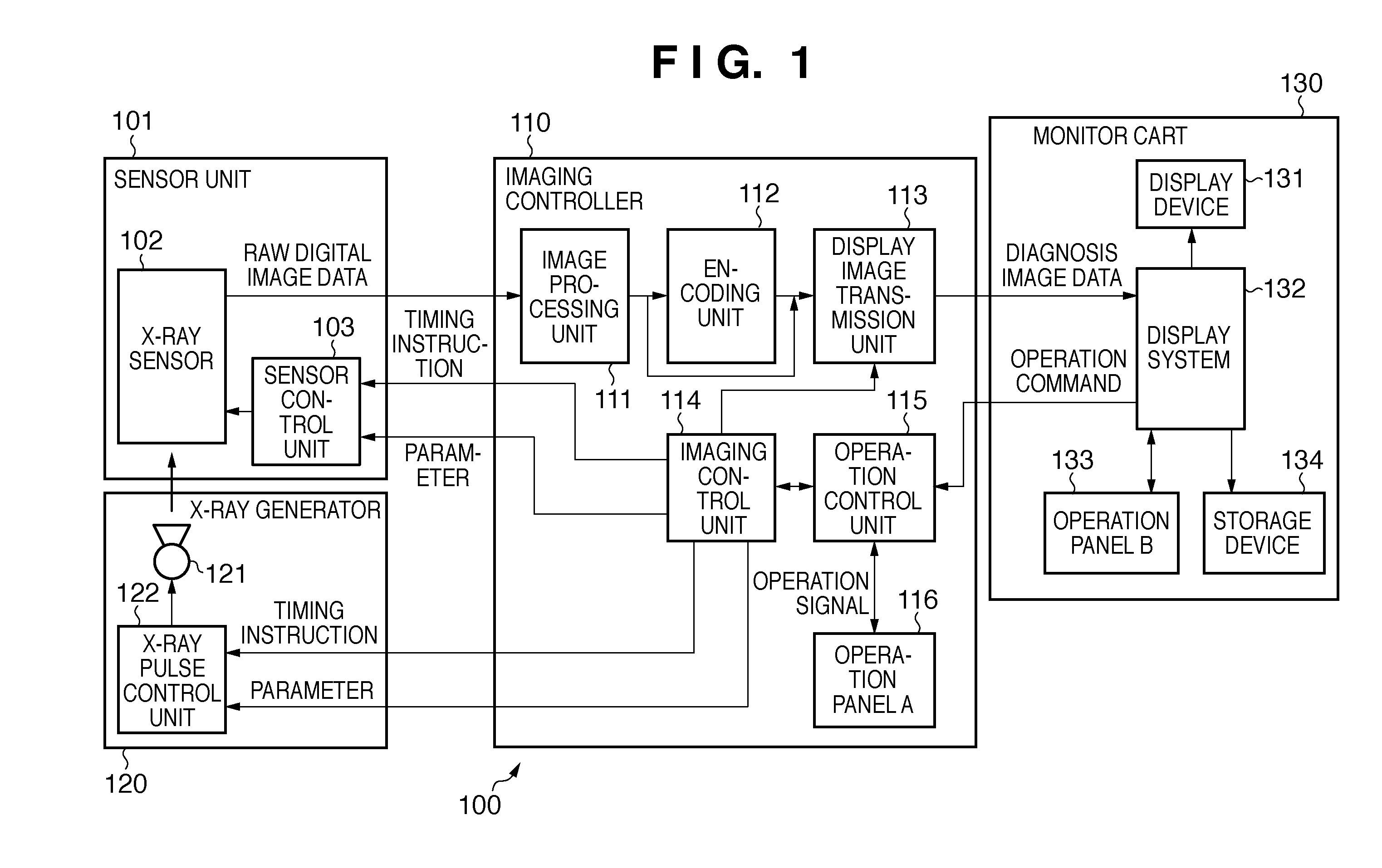
[0030]FIG. 1 is a block diagram showing the overall arrangement of an X-ray image diagnosis apparatus according to an embodiment of the present invention.

[0031]As shown in FIG. 1, an X-ray image diagnosis apparatus 100 according to this embodiment includes a sensor unit 101, an X-ray generator 120, an imaging controller 110, and a monitor cart 130.

[0032]The sensor unit 101 includes an X-ray sensor 102 and a sensor control unit 103. The X-ray sensor 102 includes, for example, a unit formed from a solid-state imaging device which senses X-rays and outputs an electrical signal corresponding to the intensity of the detected X-rays. Alternatively, the sensor unit includes a unit formed by combining a phosphor which generates fluorescence corresponding to the energy of X-rays and a photoelectric conversion element which converts the fluorescence into an electrical signal corresponding to the intensity of visible light.

[0033]The raw digital image data output from the X-ray sensor 102...

second embodiment

[0098]The first embodiment is configured such that when an imaging condition is input, the apparatus restricts the input of an imaging condition from an operation panel other than the operation panel from which the imaging condition has been input. However, the present invention is not limited to this.

[0099]For example, the apparatus may be configured to restrict the input of an irradiation start instruction from an operation panel other than the operation panel from which an imaging condition has been input. The details of this embodiment will be described below.

[0100]

[0101]FIGS. 5A and 5B are flowcharts showing a control processing sequence in an X-ray image diagnosis apparatus 100 according to the second embodiment of the present invention. Note that this flowchart is implemented by causing a microprocessor to execute control programs which are stored in the ROM and implement an imaging control unit 114 and an operation control unit 115.

[0102]In step S501, the microprocessor exec...

third embodiment

[0135]The first and second embodiments are configured such that when the operation right is set in a given operation panel, the apparatus restricts the input of any imaging condition or irradiation start instruction from another operation panel in which the operation right is not set. However, the present invention is not limited to this arrangement.

[0136]If the apparatus keeps restricting a control operation on another operation panel as in the first and second embodiments, it may restrict even a control operation to be performed in an emergency. Depending on the use case or situation of the X-ray image diagnosis apparatus, there can be a case in which it is necessary to accept even a control operation from an operation panel on which a control operation is restricted.

[0137]The third embodiment will therefore exemplify an arrangement configured to further improve the usability of an X-ray image diagnosis apparatus while avoiding the risk of starting imaging under unintended imaging...


PUM


Abstract

An X-ray image diagnosis apparatus which can accept operations from a plurality of operation panels can ensure convenience for operators while avoiding the risk of excessively exposing an object to X-rays. This invention is a control method in an X-ray image diagnosis apparatus which irradiates an object with X-rays and processes a captured image obtained by imaging the object. This method includes the steps of receiving information associated with an imaging condition at the time of X-ray irradiation which is input via an operation panel, discriminating, when the information associated with the imaging condition is received, an operation panel from which the information associated with the imaging condition has been input, and restricting, when the information associated with the imaging condition is received, the reception of a specific instruction input via an operation panel other than the discriminated operation panel.

Description

BACKGROUND OF THE INVENTION[0001]1. Field of the Invention[0002]The present invention relates to a control technique in an X-ray image diagnosis apparatus.[0003]2. Description of the Related Art[0004]Recently, in the field of X-ray image diagnosis apparatuses for medical use, apparatuses of the digital image scheme have become mainstream in place of those of the conventional analog imaging scheme. For example, the digital image scheme allows continuously captured digital images to be displayed as moving images and stored in a memory and a hard disk drive. This advantageously provides ease of use in performing diagnosis, medical treatments, and the like.[0005]In general, an X-ray image diagnosis apparatus of the digital image scheme includes an imaging apparatus body which irradiates X-rays and generates radiographed images based on data read from a sensor panel. This apparatus also includes an operation panel to input imaging conditions to be set in the imaging apparatus body and is...

Claims


Application Information

Patent Timeline
Patent Type & Authority Applications(United States)
IPC IPC(8): H05G1/58
CPCA61B6/00A61B6/467A61B6/107A61B6/10A61B6/54A61B6/548
Inventor MATSUMOTO, SHINICHI
Owner CANON KK
Why Eureka
Try Eureka