Board appearance inspection method and device

Inactive Publication Date: 2010-02-04
I-PULSE CO LTD
View PDF2 Cites 13 Cited by
  • Summary
  • Abstract
  • Description
  • Claims
  • Application Information

AI Technical Summary

Benefits of technology

[0007]Such a technical problem can be solved by a board appearance inspection method according to the present invention, which is configured as described below.
[0008]That is, the present invention is a method for carrying out an appearance inspection of a board, comprising: an image pickup step for picking up an image of the board using image pickup device; an automatic judgment step for comparing a picked-up image of the board obtained in the image pickup step with standard image data stored in advance in memory as a standard of a go

Problems solved by technology

With the pattern matching method, composing the standard image data from a single sample image severely limits the number of boards judged to be good and gives rise to a risk where even boards that should be judged to be good in a visual inspection by an operator may end up being discarded as poor boards.
Therefore, while a range of the standard image data is desirably given a certain degree of latitude, immoderately widening the standard image data range will now cause boards tha

Method used


Image

  • Board appearance inspection method and device
  • Board appearance inspection method and device
  • Board appearance inspection method and device

Examples


first embodiment

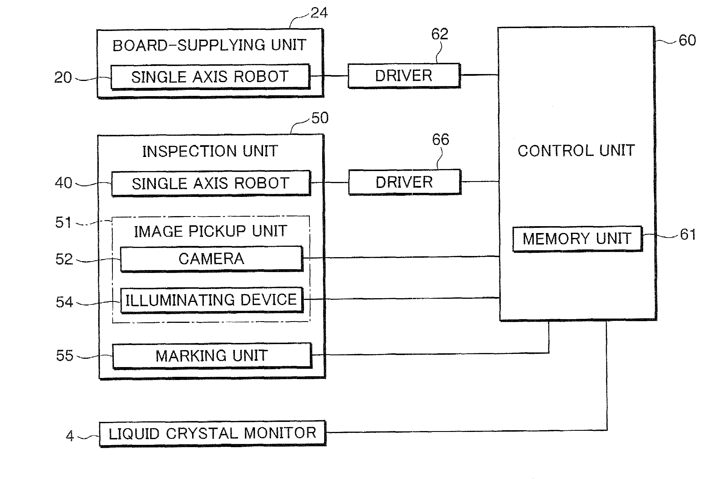
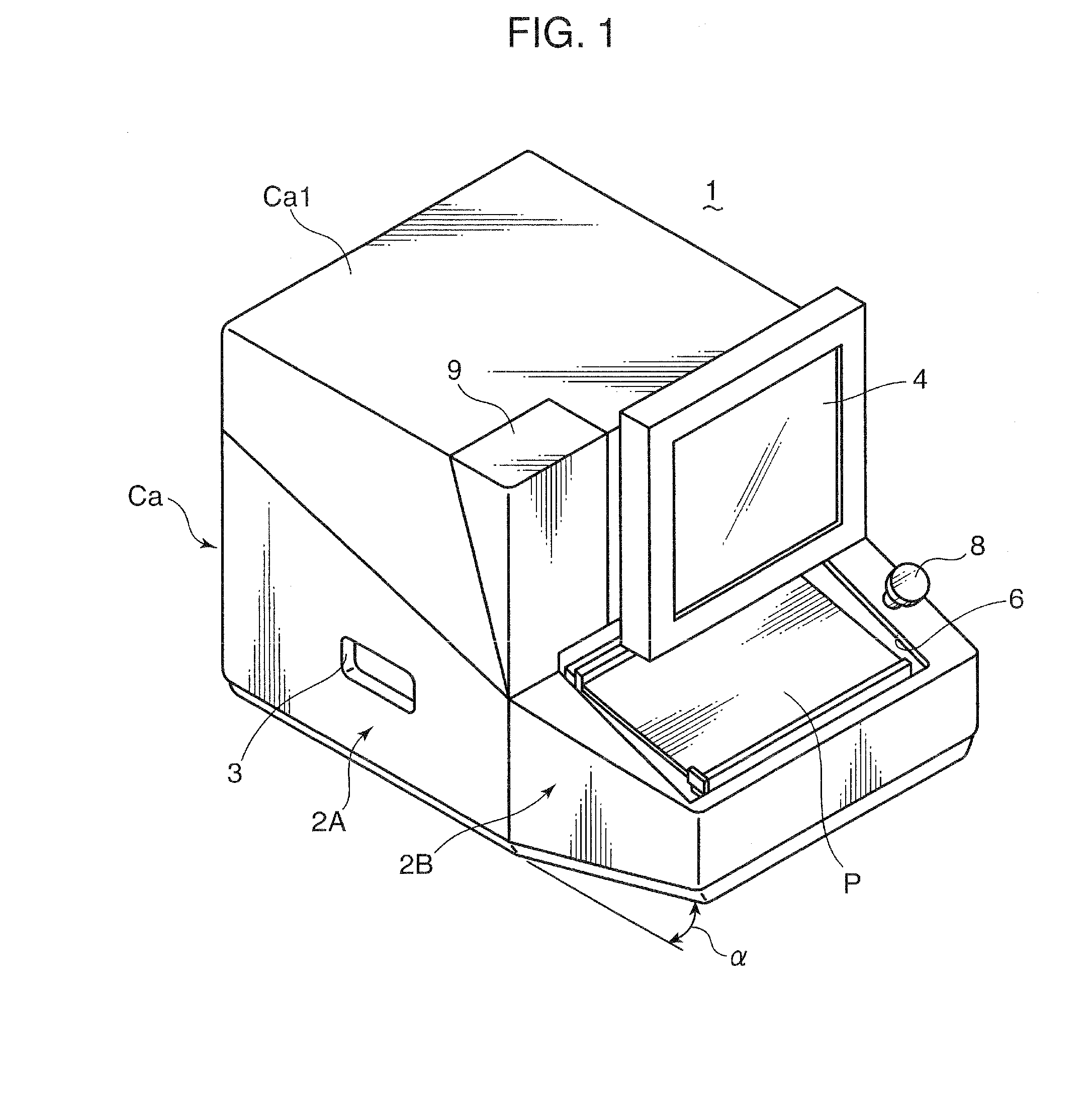
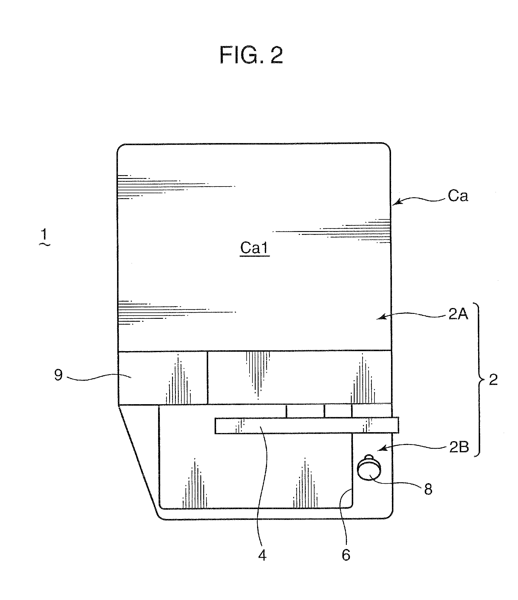
[0037]FIGS. 1 and 2 schematically show a board inspection device 1 according to a first embodiment of the present invention. As shown in the drawings, the inspection device 1 has an A-shaped appearance configuration as viewed laterally in which the entire inspection device 1 is shaped like a box, and is provided with: a rear-side portion 2A constituting a posterior side of the inspection device 1; and a front-side portion 2B that extends forward from a front end lower portion of the rear-side portion 2A. The appearance of such an inspection device 1 is formed by a casing Ca that covers internal parts such as an inspection unit 50 to be described later.

[0038]Among the inspection device 1, the front-side portion 2B is provided with an inlet / outlet 6 for taking out and / or putting in a print board P from / to the device. The inlet / outlet 6 is composed of an opening formed on the casing Ca and is provided centrally in the width direction (in FIG. 2, at the center in the horizontal directio...

second embodiment

[0102]FIG. 14 schematically shows a board inspection system according to the second embodiment of the present invention. A board inspection system 10 shown in the present drawing comprises a plurality (five in the example shown) of horizontally aligned inspection devices 1a, 1b, 1b, . . . which are network-connected via a hub 70. The respective inspection devices 1a, 1b, 1b, . . . share the same basic structure as the inspection device 1 according to the first embodiment, and are provided with a function for judging whether a print board P (refer to FIG. 1 and the like) supplied by the operator is good or poor by picking up an image of the print board P and performing image processing or the like thereon. Among the inspection devices, a central inspection device 1a is provided with, in addition to a function for performing inspection processing such as described above, a function for displaying an image of a print board P judged by the device itself (the inspection device 1a) or ano...

third embodiment

[0131]It is assumed that an inspection device having a similar structure to the inspection device 1 according to the first embodiment is used in the present third embodiment, and a specific structure thereof is as shown in FIGS. 1 to 7. However, the inspection device according to the present third embodiment (hereinafter referred to as the inspection device 1) differs from the first embodiment in the mode of images displayed on a liquid crystal monitor 4 for a visual judgment by an operator. As such, a description will be given below focusing on this point.

[0132]With the inspection device 1 according to the present embodiment, after an appearance inspection of a print board P is performed by a control unit 60, a picked-up image of a portion judged to be poor by the control unit 60 is displayed on a liquid crystal monitor 4 and a visual judgment by an operator is performed. The poor portion displayed on the liquid crystal monitor 4 displays a difference image between an image of the ...


PUM


Abstract

Problem to be Solved To efficiently perform a board appearance inspection with a simple structure.
Solution A control unit 60 performs processing for comparing a picked-up image of a board P picked up by a camera 52 with standard image data stored in a memory unit 61 and judging whether the board is good or poor. When the board P is judged to be poor, an image of the board P is displayed on a liquid crystal monitor 4 in order to have an operator visually judge the board P. When the board P is judged to be good by the visual judgment, the picked-up image of the board P that is judged to be good is additionally stored in the memory unit 61 as the standard image data.

Description

TECHNICAL FIELD[0001]The present invention relates to a method and device for inspecting the appearance of a board such as a mounting state of parts mounted on the board, a printed wiring pattern on the board, a cream solder printing pattern on the board and the like.BACKGROUND ART[0002]A conventional method for performing an appearance inspection of a board involves comparing a picked-up image of a board with standard image data (master data) to be used as a standard of a good board and inspecting the degree of coincidence between the two (so-called pattern matching method). With the pattern matching method, composing the standard image data from a single sample image severely limits the number of boards judged to be good and gives rise to a risk where even boards that should be judged to be good in a visual inspection by an operator may end up being discarded as poor boards. Therefore, while a range of the standard image data is desirably given a certain degree of latitude, immode...

Claims


Application Information

Patent Timeline
IPC IPC(8): G06K9/00
CPCG01N21/95607G01N21/95684H05K3/3484G01N2021/95638H05K1/0269G01N2021/95615H05K3/3485
Inventor KAKUDA, YOSHIHISA
Owner I-PULSE CO LTD
Why Eureka
Try Eureka