

Image Processor and Image Processing Method
- Summary
- Abstract
- Description
- Claims
- Application Information
AI Technical Summary
Benefits of technology
Problems solved by technology
Method used
Image

Examples
Embodiment Construction
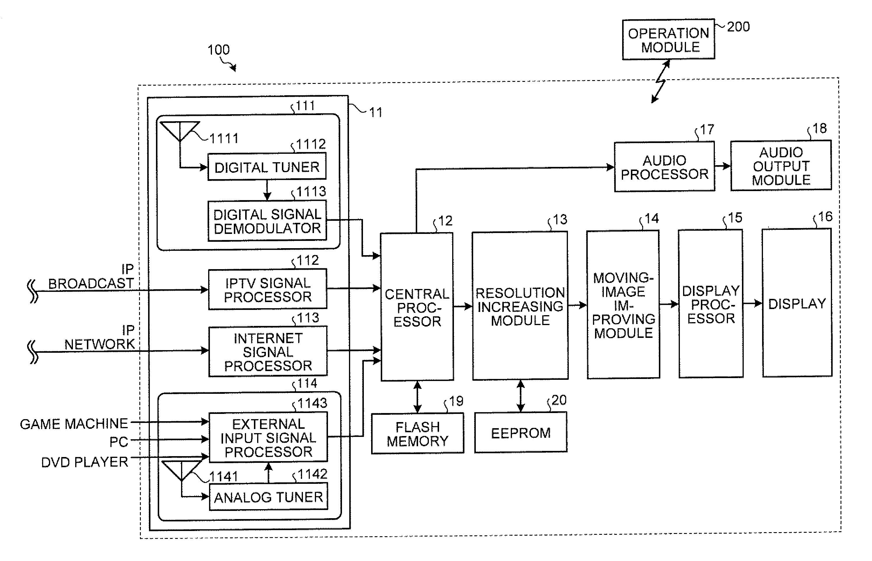
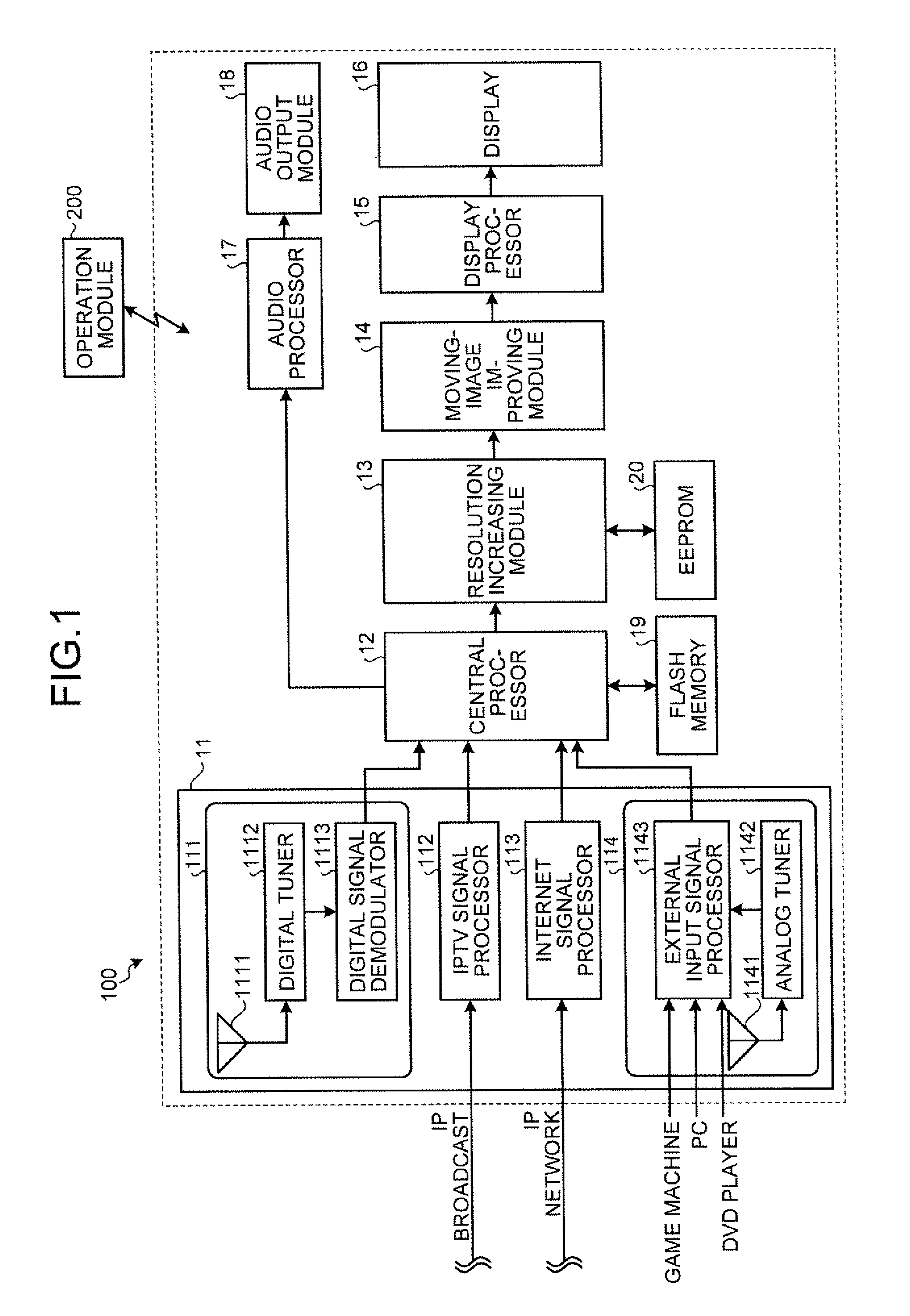
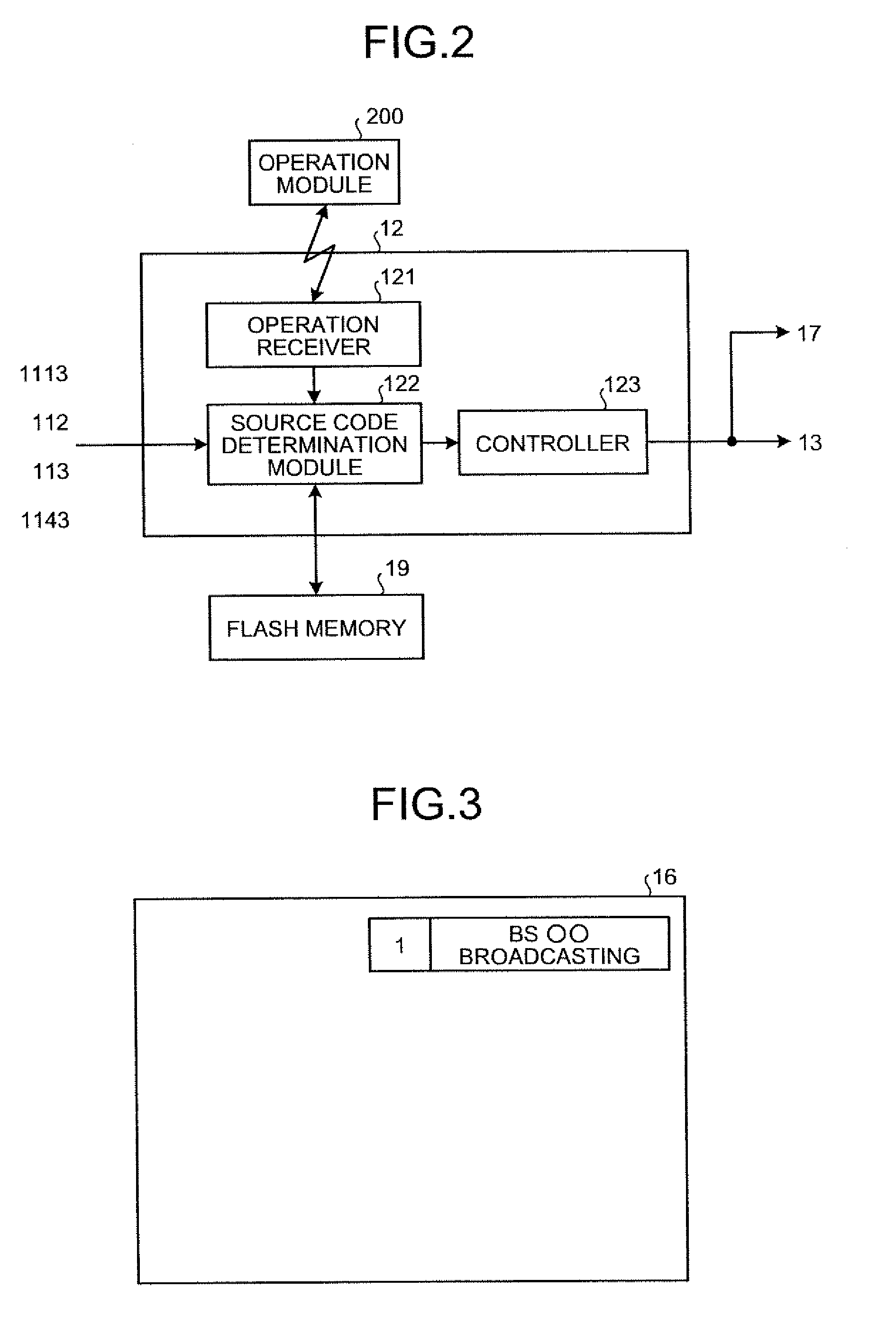
[0021]Various embodiments according to the invention will be described hereinafter with reference to the accompanying drawings. In general, according to one embodiment of the invention, an image processor has a resolution increase module, a detector, and a controller. The resolution increase module is configured to perform super-resolution processing by increasing, upon receipt of a first video signal having a first resolution, pixels by estimating an original pixel value from the first video signal, so as to restore the first video signal to a second video signal having a second resolution higher than the first resolution. The detector is configured to detect at least one of an information amount of the first video signal, a noise amount of the first video signal, and a type of a terminal to which the first video signal is input. The controller is configured to change a degree of the super-resolution processing performed by the resolution increase module based on a detection result...
PUM
 Abstract
Description
Claims
Application Information