System and Method for Pseudo-Continuous Measurement of Metabolite Concentrations in a Mammalian Body

a technology of pseudo-continuous measurement and metabolite concentration, applied in the direction of pressure pumps, bends, siphons, etc., can solve the problems of difficult to achieve and accurately maintain such low flow rates, commercial products based on this technique are plagued, and the pump structure is typically relatively expensiv

Inactive Publication Date: 2010-02-04
G SENSE LTD
View PDF21 Cites 29 Cited by
  • Summary
  • Abstract
  • Description
  • Claims
  • Application Information

AI Technical Summary

Problems solved by technology

Commercial products based upon this technique are plagued by a number of practical problems.
In practice, it has been found difficult to achieve and accurately maintain such low flow rates.
Secondly, these systems typically require precise coordinated control of two separate fluid flow rates, a first for the dialysate and a second for a reagent added to the dialysate downstream of the microdialysis probe.
As a result, the pump structure is typically relatively expensive and must be doubled up to regulate both fluids.
This requirement for precision is further compounded by the extremely low flow rates mentioned above, together presenting a very serious hurdle to practical implementation of such systems.
Thirdly, and possibly most problematic, the existing systems all suffer from very significant drift in the accuracy of results due to deposition and other interactions of the fluid with surfaces of the sensor, or in the case of optical sensors, possibly with surfaces of vessels interposed between the fluid and the sensor.
For optical sensing, over the course of hours of use of the sensor, an indicator generated by the reagent may build up on surfaces of the sensor or vessel facing the fluid, thereby affecting the optical absorbance detected by the sensor and causing drift of measurements.
As a result of this problem, various sensors of this type currently commercially available require frequent recalibration by the user, and their results are not considered sufficiently reliable as a basis for clinical decisions.
Since each device includes costly components of the sensor itself and the other electronic components required for operation, replacement of the device every few days renders it expensive for ongoing use.

Method used


Image

  • System and Method for Pseudo-Continuous Measurement of Metabolite Concentrations in a Mammalian Body
  • System and Method for Pseudo-Continuous Measurement of Metabolite Concentrations in a Mammalian Body
  • System and Method for Pseudo-Continuous Measurement of Metabolite Concentrations in a Mammalian Body

Examples


Embodiment Construction

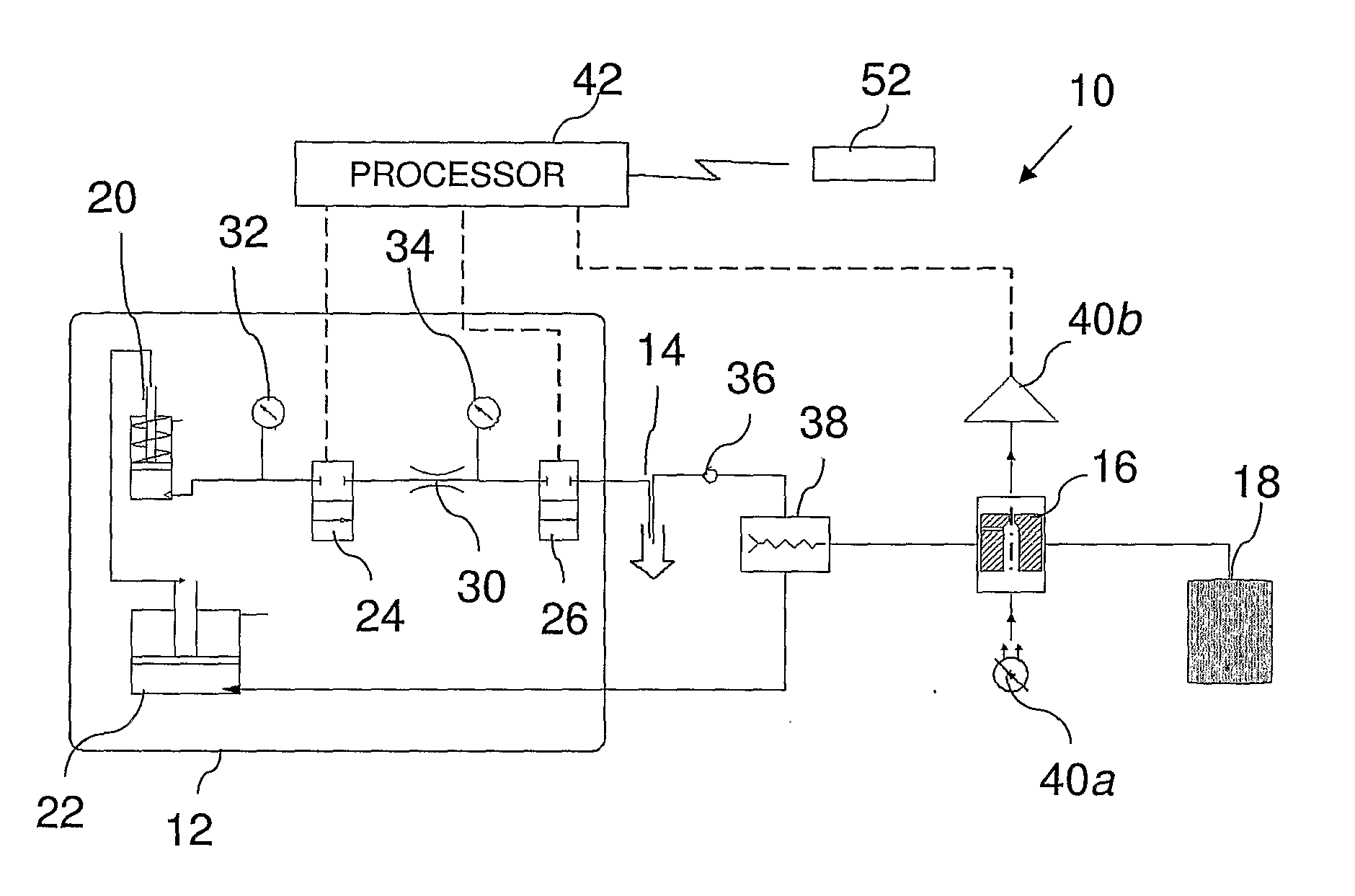
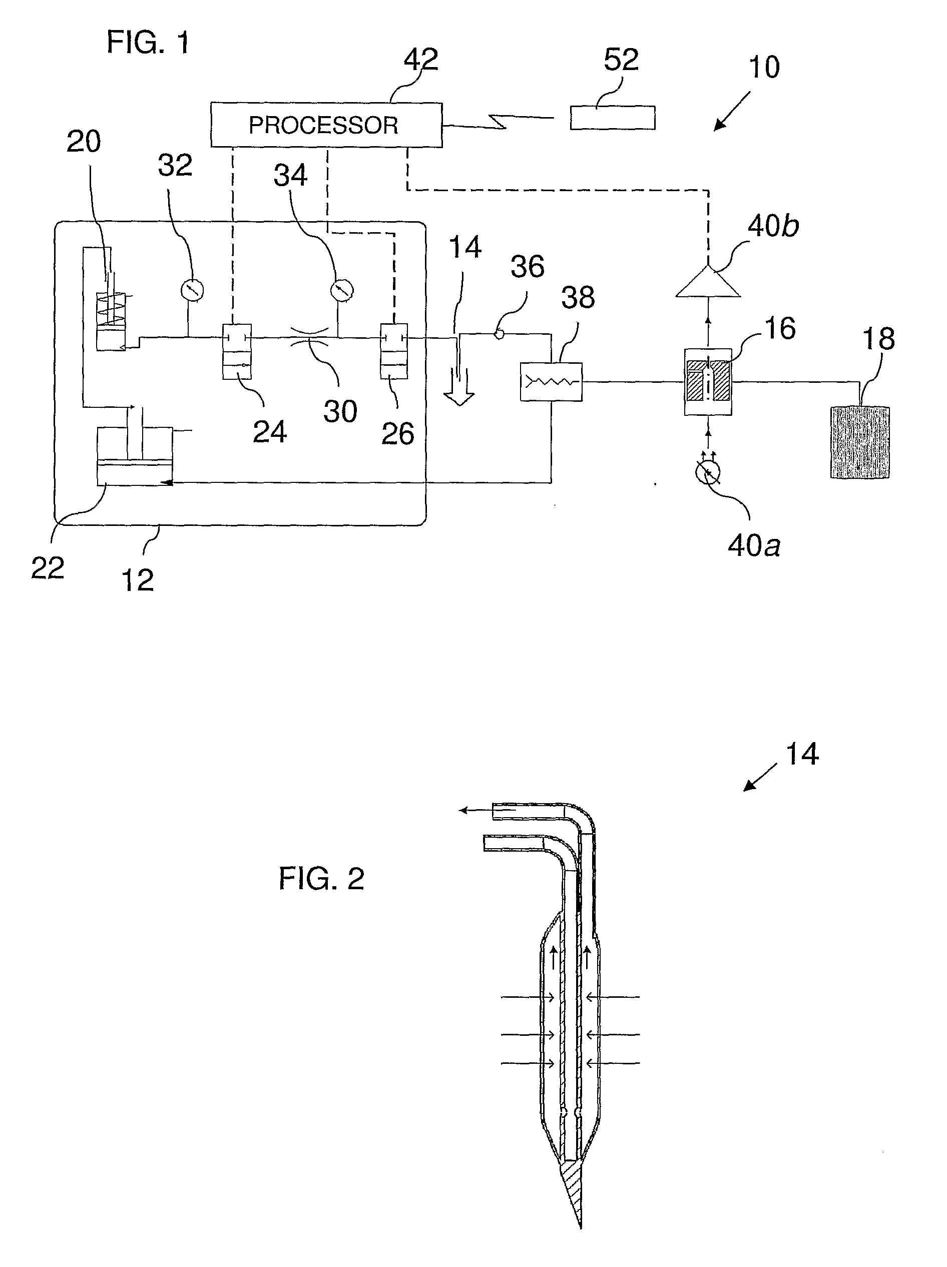
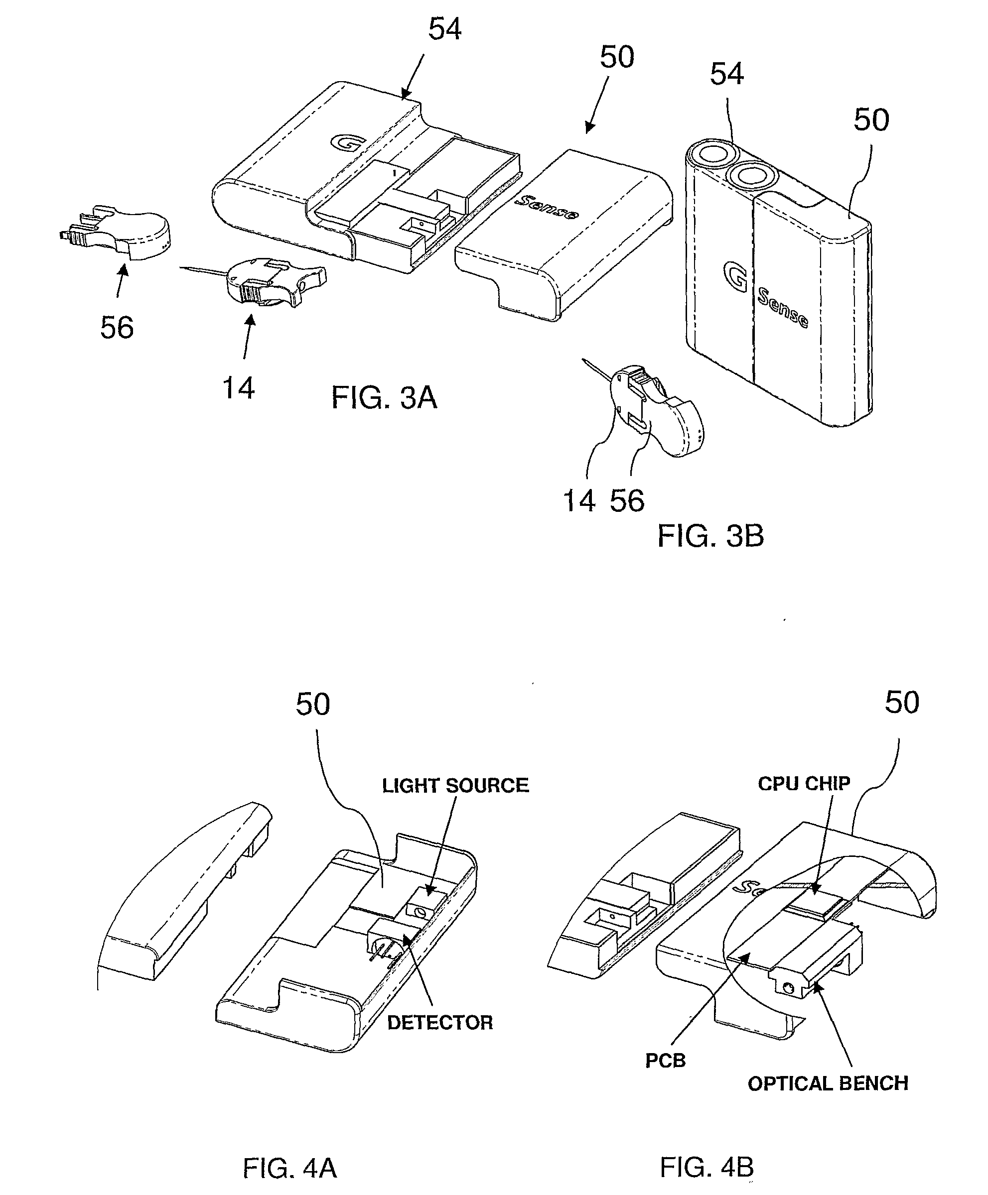
[0044]The present invention is a system for monitoring of metabolite concentration within a human or animal body, and various components of such a system.

[0045]Before addressing the drawings, by way of a general introduction, the systems of the present invention are believed to have four primary sets of features, each of independent utility and patentable significance in its own right, which may be combined in synergy to provide further advantageous configurations of the present invention. These four primary sets of features will first be set out briefly below, followed by a more extensive description of one particularly preferred embodiment of the invention which implements all four of these sets of features. Although primary emphasis will be placed on these four sets of features, it should be noted that this emphasis is not intended to negate the patentable significance of various other significant features described below, even where they do not fall into one of these four catego...


PUM

PropertyMeasurementUnit
lengthaaaaaaaaaa
pressureaaaaaaaaaa
volumesaaaaaaaaaa

Abstract

A metabolite monitoring system comprising a microdialysis probe including a semi-permeable membrane and a probe flow path passing from an inlet through a sensing volume adjacent to said semi-permeable membrane to an outlet, a fluid delivery device for delivering dialysate to said inlet; and a metabolite monitoring system associated with said outlet for monitoring a concentration of at least one metabolite in said dialysate from said microdialysis probe, wherein said fluid delivery device is configured to deliver a pulsed flow of said dialysate to said inlet.

Description

FIELD AND BACKGROUND OF THE INVENTION[0001]The present invention relates to body fluid monitoring and, in particular, it concerns a system and method for pseudo-continuous measurement of metabolite concentrations in a mammalian body, and especially of glucose.[0002]It has been proposed to measure concentrations of a metabolite in a mammalian body by use of a microdialysis probe inserted into the body through which a dialysate passes and absorbs metabolites from the surrounding body fluids. Of particular importance are applications to monitoring of glucose concentrations, which are critical to management of diabetes. Examples of such systems are described in the following U.S. Pat. Nos. 3,512,517; 4,221,567; 4,694,832; 4,765,339; 5,640,954; 6,013,029; and 6,852,500.[0003]Commercial products based upon this technique are plagued by a number of practical problems. Firstly, in order to enhance the concentrations of metabolites in the dialysate, and to minimize the size and weight of flu...

Claims


Application Information

Patent Timeline
Patent Type & Authority Applications(United States)
IPC IPC(8): A61B5/00G01N15/06
CPCA61B5/14525A61B5/14532A61B5/157A61B5/1495A61B5/1459Y10T137/2883Y10T137/218Y10T137/2931Y10T137/2185
Inventor SHEKALIM, AVRAHAMPELEG, NOAM
Owner G SENSE LTD
Why Eureka
Try Eureka