

Polar modulation transmission apparatus
- Summary
- Abstract
- Description
- Claims
- Application Information
AI Technical Summary
Benefits of technology
Problems solved by technology
Method used
Image

Examples
Embodiment Construction
[0053]Embodiments of the present invention will be described in detail with reference to the accompanying drawings.
[0054](1) Overall Configuration
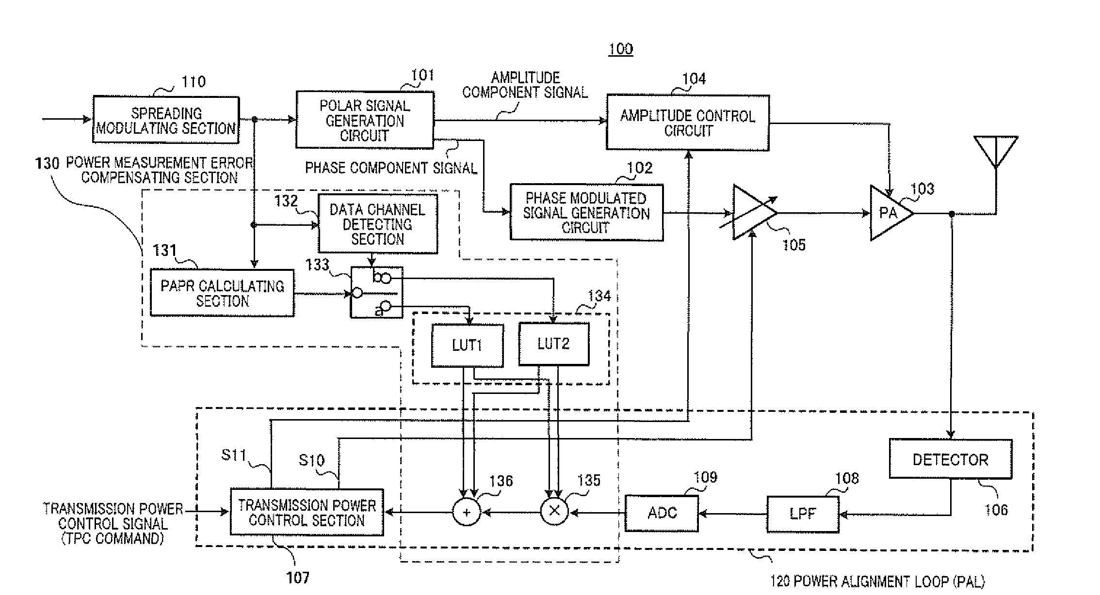
[0055]FIG. 3-1 and FIG. 3-2 show the configuration of the polar modulation transmission apparatus according to an embodiment of the present invention. Polar modulation transmission apparatus 100-2 of FIG. 3-2 has the same basic configuration as polar modulation transmission apparatus 100 of FIG. 3-1, and therefore, in the following explanation, the configuration of polar modulation transmission apparatus 100 of FIG. 3-1 will be mainly explained.
[0056]Polar modulation transmission apparatus 100 of FIG. 3-1 has polar signal generation circuit 101, phase modulated signal generation circuit 102, power amplifier (PA) 103, amplitude control circuit 104, variable amplifier 105 formed with a variable gain amplifier (VGA) and / or an attenuator, and power alignment loop 120.
[0057]Power alignment loop 120 has detector 106 that detects the output power...
PUM
 Abstract
Description
Claims
Application Information