
Laser module group with controllable power

A laser module and power technology, which is applied in the direction of the device for controlling the output parameters of the laser, can solve the problems of complex structure, difficulty in large-scale production, and cumbersome process of the power controllable laser module, so as to improve mass production efficiency and accurate power The effect of simple control and production process

Inactive Publication Date: 2015-09-16
丹东依镭社电子科技有限公司
View PDF4 Cites 0 Cited by
  • Summary
  • Abstract
  • Description
  • Claims
  • Application Information

AI Technical Summary

Problems solved by technology

[0002] At present, the power controllable laser module has complex structure, cumbersome process and too large volume, making it difficult to realize mass production.

Method used


Image

  • Laser module group with controllable power
  • Laser module group with controllable power
  • Laser module group with controllable power

Examples


Embodiment Construction

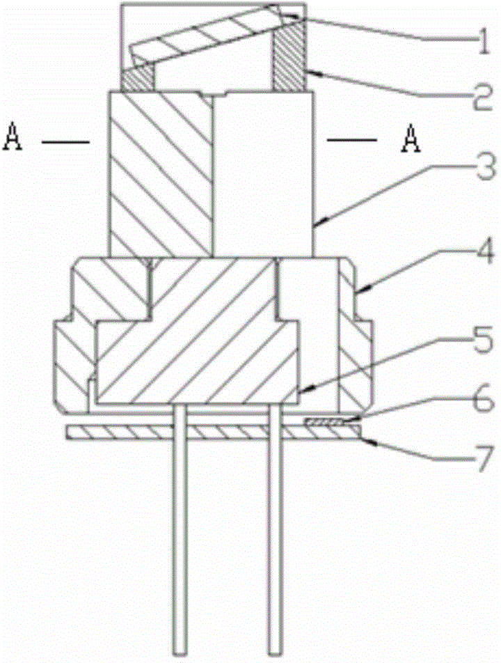
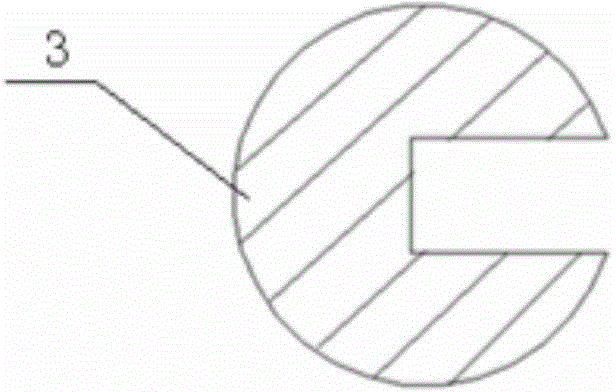
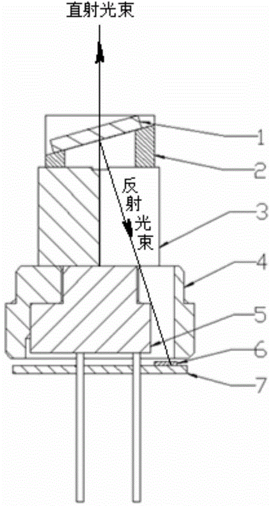
[0012] like figure 1 , 2 As shown, a power controllable laser module includes LD5, LD driver board 7, sensor 6, bearing seat 4, photoresist crystal 3, transflective glass sheet 1 and bracket 2, and the bottom surface of the bearing seat 4 is set The light transmission hole, the LD5 is installed in the bearing seat 4; the sensor 6 is welded on the LD driving board 7, and the LD driving board 7 is installed under the bearing seat 4, and the sensor 6 and The light-transmitting hole corresponds; the light-resist crystal 3 is mounted on the LD5, and a gap is set on the light-resist crystal 3, and the gap corresponds to the light-transmitting hole; the bracket 2 is installed on the On the optical glue crystal 3, the semi-transparent and semi-reflective glass sheet 1 is installed on the support 2, and the semi-transparent and semi-reflective glass sheet 1 forms a certain angle with the laser beam emitted by the LD5 to make the semi-transparent and semi-reflective glass sheet 1 form ...


PUM


Abstract

The invention relates to a laser module group, particularly to a laser module with a controllable power. On the basis of the technical scheme, the laser module group is composed of an LD, an LD driver panel, a sensor, a bearing seat, an optical cement crystal, a semi-transparent and semi-transparent glass sheet, and a bracket. A light-transmitting hole is formed in the bottom of the bearing seat; and the LD is installed inside the bearing seat. The sensor is welded to the LED driver panel that is installed below the bearing seat; and the sensor corresponds to the light-transmitting hole. The optical cement crystal is installed on the LED; a notch corresponding to the light-transmitting hole is formed in the optical cement crystal; the bracket is installed on the optical cement crystal; and the semi-transparent and semi-transparent glass sheet is installed on the bracket. A certain angle is formed between the semi-transparent and semi-transparent glass sheet and a laser beam emitted by the LD, so that the laser beam reflected by the semi-transparent and semi-transparent glass sheet is emitted on the sensor through the notch and the light-transmitting hole. The laser module group has advantages of simple and compact structure, small size, and simple production process; and the batch production efficiency is effectively improved.

Description

technical field [0001] The invention relates to a laser module, in particular to a power controllable laser module. Background technique [0002] At present, the power controllable laser module has complex structure, cumbersome process, and large volume, making it difficult to achieve mass production. Contents of the invention [0003] The invention provides a power-controllable laser module, which has a simple and compact structure, a small volume, a simple production process, and effectively improves mass production efficiency. [0004] Technical scheme of the present invention is as follows: [0005] A power-controllable laser module, including LD, LD drive board, sensor, bearing seat, laser crystal, transflective and semi-reflective glass sheet and bracket, the bottom surface of the bearing base is provided with a light-transmitting hole, and the LD is installed on the In the bearing seat; the sensor is welded on the LD driver board, the LD driver board is installed ...

Claims


Application Information

Patent Timeline
Patent Type & Authority Applications(China)
IPC IPC(8): H01S5/06
Inventor 何振新初志刚
Owner 丹东依镭社电子科技有限公司
Learn More