
Heat Dissipation System for Computers

a heat dissipation system and computer technology, applied in the field of heat dissipation, can solve the problems of processor becoming incapable of processing a part of a task, the rotation speed of the heat dissipating fan will increase, and the performance control portion temporarily reduces the processing capability of the processor, so as to maximize the level of user comfort

Active Publication Date: 2010-02-04
LENOVO PC INT
View PDF5 Cites 54 Cited by
  • Summary
  • Abstract
  • Description
  • Claims
  • Application Information

AI Technical Summary

Benefits of technology

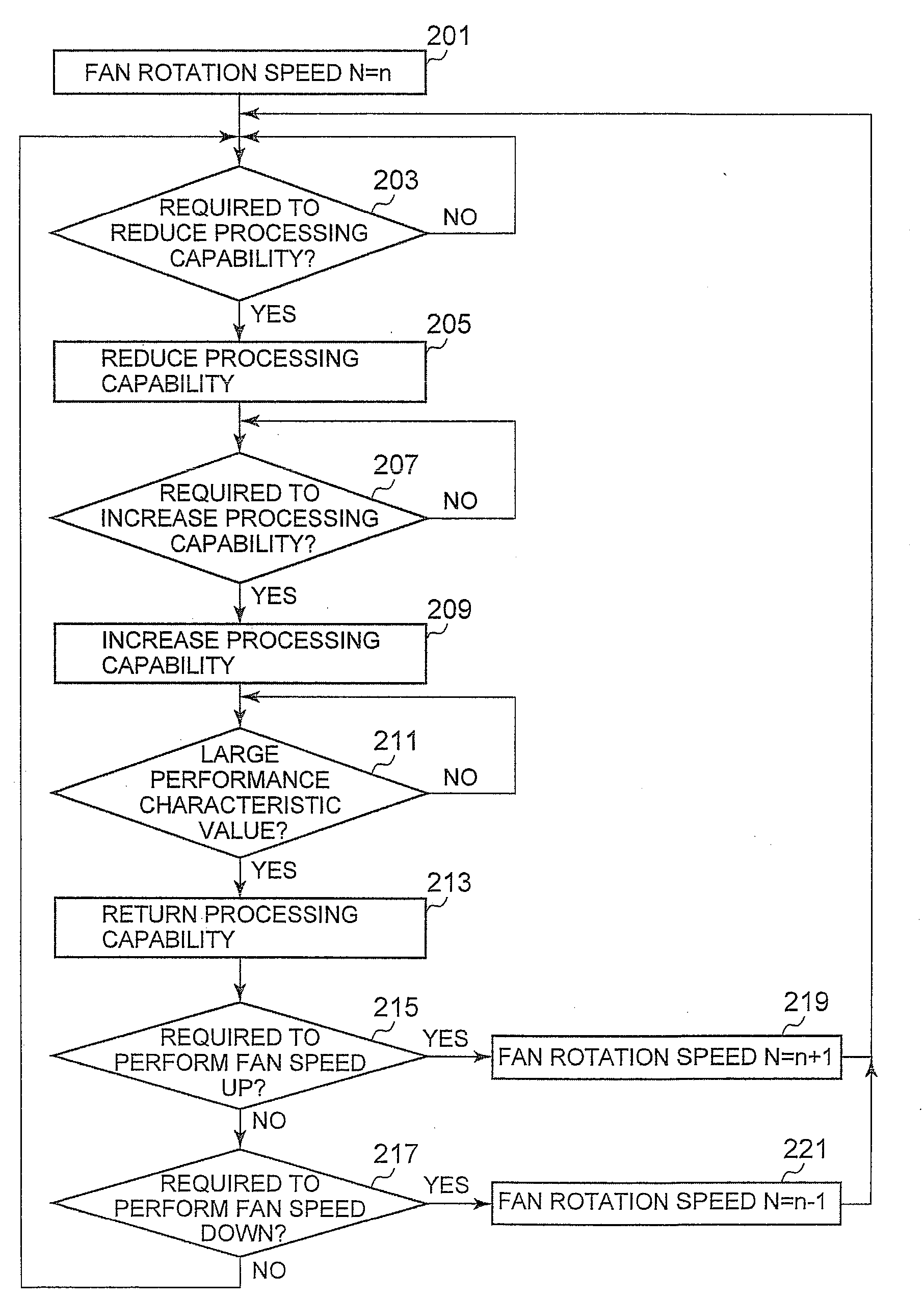
"The present invention aims to harmonize the processing capability and noise levels of a computer by balancing the processing capability of the processor and the rotation speed of the heat dissipating fan. The invention includes a heat dissipating fan, temperature sensor, and processor. A performance control portion reduces the processing capability of the processor when the temperature sensor measures a threshold temperature. The processing capability is reduced to decrease the amount of heat generated. The heat dissipating fan increases its rotation speed in a stepwise manner when the processing capability is reduced. The invention also includes a temperature prediction portion and a processing capability setting portion to minimize the reduction in processing capability and prevent abrupt rise in heat generation. The processing capability setting portion can adjust the processing capability based on the performance characteristic value to harmonize between the users' preference and the operation status. The invention reduces overcooling and achieves thermal balance by using hysteresis characteristics for the rotation control of the heat dissipating fan."

Problems solved by technology

A performance control portion temporarily reduces the processing capability of the processor when it is predicted that the measurement temperature measured by the temperature sensor exceeds a threshold temperature in a predetermined period of time so the rotation speed of the heat dissipating fan will increase.
In a heavy load time zone, because the processing capability has been reduced, the processor becomes unable to process a part of a task that otherwise could be processed if the processing capability was not reduced.

Method used


Image

  • Heat Dissipation System for Computers
  • Heat Dissipation System for Computers
  • Heat Dissipation System for Computers

Examples


Embodiment Construction

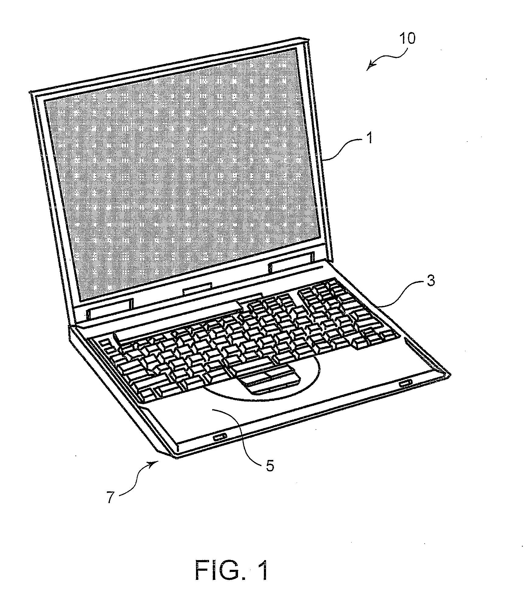
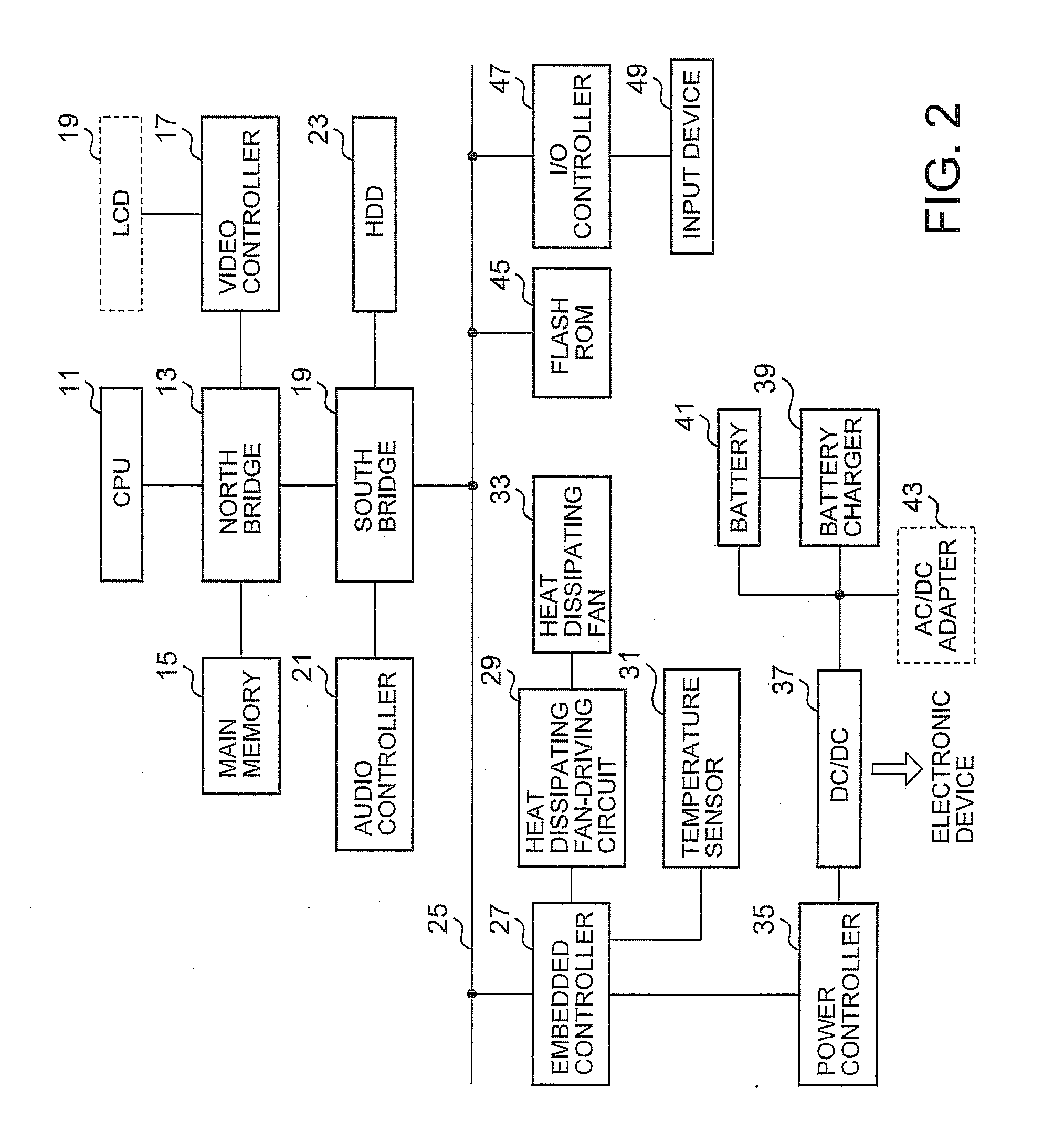
[0032]Referring now to the drawings and in particular to FIG. 1, there is depicted an external perspective view of a note PC 10, in accordance with a preferred embodiment of the present invention. FIG. 2 is a block diagram of the note PC 10. The note PC 10 includes a system housing 3 in which a keyboard is mounted on a surface thereof and electronic components are accommodated and an LCD housing 1. The system housing 3 has mounted therein a set of electronic components that is depicted as a solid block in FIG. 2. During the usage of the note PC 10, a bottom surface 7 of the note PC 10 makes contact with user's laps and a palm rest 5 makes contact with user's hands. Therefore, the surface of the system housing 3 needs to be maintained at a predetermined temperature or lower, and for this purpose, a forced air-cooling type heat dissipation system has been conventionally employed in the note PC 10.

[0033]A CPU 11 is an arithmetic processing device performing the central function of the ...


PUM


Abstract

A heat dissipation system within a housing of a computer is disclosed. The heat dissipation system includes a heat dissipating fan, a temperature sensor, a rotation speed setting portion, and a performance control portion. The rotation speed setting portion is configured to change a rotation speed of the heat dissipating fan in a stepwise manner based on a threshold temperature and a measurement temperature measured by the temperature sensor. The performance control portion is configured to temporarily reduce the processing capability of a processor within the computer in response to a determination that the measurement temperature has exceeded the threshold temperature during a predetermined period of time.

Description

PRIORITY CLAIM[0001]The present application claims benefit of priority under 35 U.S.C. §§120, 365 to the previously filed Japanese Patent Application No. JP2008-200288 entitled, “Heat Dissipation System for Computer” with a priority date of Aug. 2, 2008, which is incorporated by reference herein.BACKGROUND OF THE INVENTION[0002]1. Technical Field[0003]The present invention relates to heat dissipation in general, and in particular to a method for managing the speed of a heat dissipating fan for a computer system while harmonizing the processing capability of a processor within the computer system.[0004]2. Description of Related Art[0005]A notebook personal computer (note PC) typically includes many electronic components, such as processors, memories, video cards, etc., which are mounted in high-density within a housing. Such electronic components tend to emit heat during the operation of the note PC, which raises the temperature of the electronic components as well as the housing. A ...

Claims


Application Information

Patent Timeline
Patent Type & Authority Applications(United States)
IPC IPC(8): G05D23/19G06F3/048G06F9/318
CPCY02B60/1275G06F1/206Y02D10/00
Inventor SHIMOTONO, SUSUMUNAKAMURA, FUSANOBU
Owner LENOVO PC INT
Learn More