Engine Oil Level Management System and Method of Assembling Engines in Vehicles

a technology of engine oil level management and engine, applied in the direction of pressure lubrication, lubrication of auxiliaries, lubrication elements, etc., can solve the problems of reducing oil life, oil becomes aerated, oil pressure decreases, etc., and achieves the effect of not decreasing oil pressure, oil temperature and spin loss, and reducing aeration

Active Publication Date: 2010-02-11
GM GLOBAL TECH OPERATIONS LLC
View PDF14 Cites 15 Cited by
  • Summary
  • Abstract
  • Description
  • Claims
  • Application Information

AI Technical Summary

Benefits of technology

[0004]An oil level management system for a vehicle is provided with an oil pan having a unique configuration to manage the oil level to prevent contact with the rotating crankshaft, thereby decreasing aeration, oil temperature and spin losses and not decreasing oil pressure. Additionally, the oil pan is configured to provide these benefits, whether the engine is used in a front wheel-drive or a rear wheel-drive vehicle. Specifically, the oil pan is configured to contain oil and to be mountable to the engine block and has a baffle extending transverse to the axis of rotation of the engine crankshaft when the oil pan is so mounted. The baffle is configured to partially define a first oil reservoir and a second oil reservoir, as well as an oil flow opening such that the oil reservoirs are in fluid communication with one another and are characterized by respective first and second oil levels within the pan. The second reservoir drains to the first reservoir when the engine is running and when the engine block and crankshaft are positioned on the vehicle such that the axis of rotation is tilted from horizontal. The first oil level is lower than the second oil level to avoid oil contact with the crankshaft. An internal combustion engine including the oil pan described above is also provided.

Problems solved by technology

If the moving parts contact the oil collected in the oil pan, the oil pressure decreases while the oil temperature increases, reducing oil life.
Additionally, the oil becomes aerated, and is less efficient at cooling the engine.
The oil contact also contributes to spin losses, reducing engine power.

Method used


Image

  • Engine Oil Level Management System and Method of Assembling Engines in Vehicles
  • Engine Oil Level Management System and Method of Assembling Engines in Vehicles
  • Engine Oil Level Management System and Method of Assembling Engines in Vehicles

Examples


Embodiment Construction

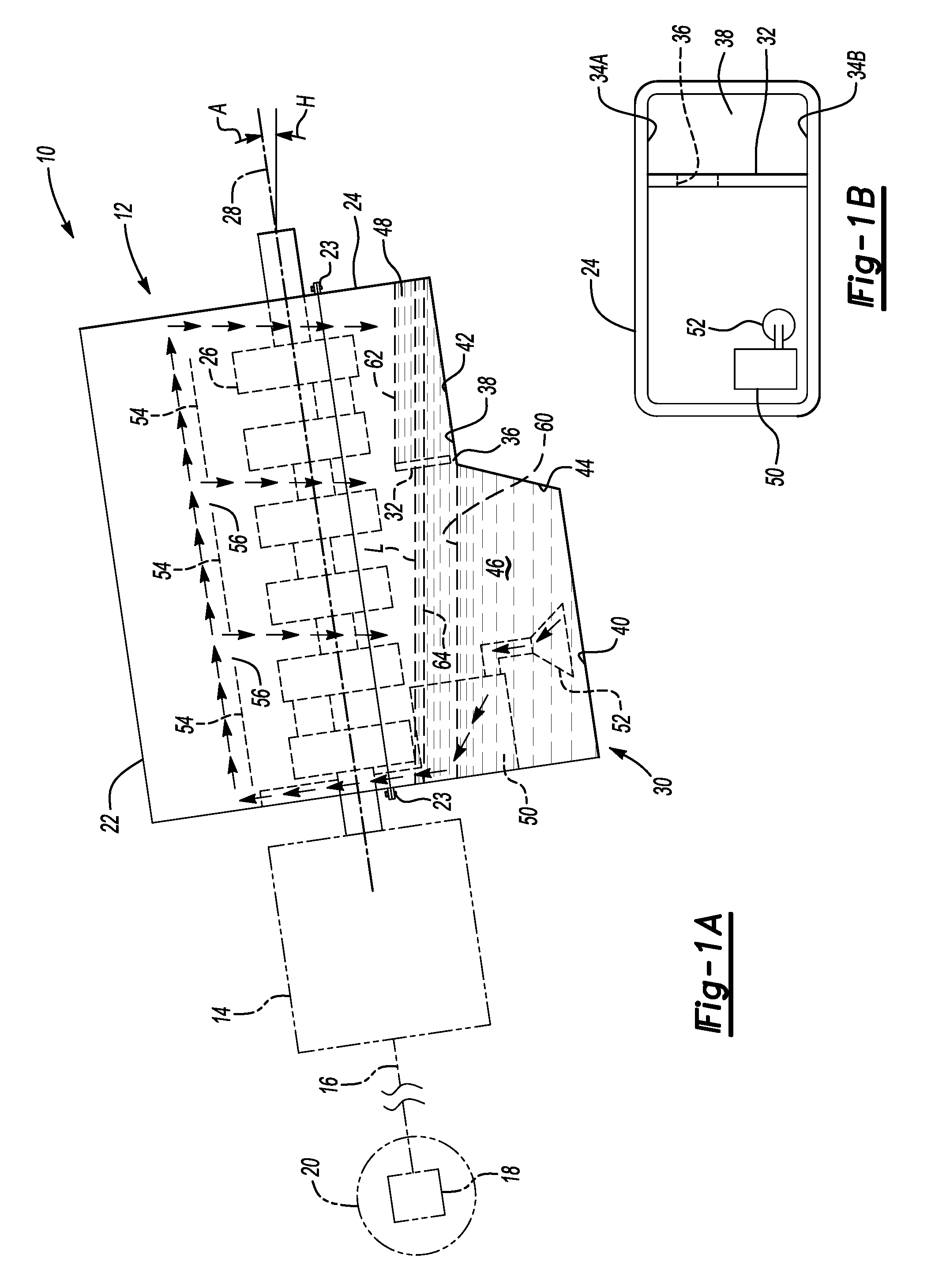
[0014]Referring to the drawings wherein like reference numbers refer to like components, FIG. 1A shows a vehicle 10 arranged as a rear wheel-drive vehicle having an engine 12 operatively connected with a transmission 14. The transmission 14 is operatively connected through a driveshaft 16 and differential mechanism 18 to left and right rear wheels 20 (only right rear wheel 20 visible in side view and not to scale).

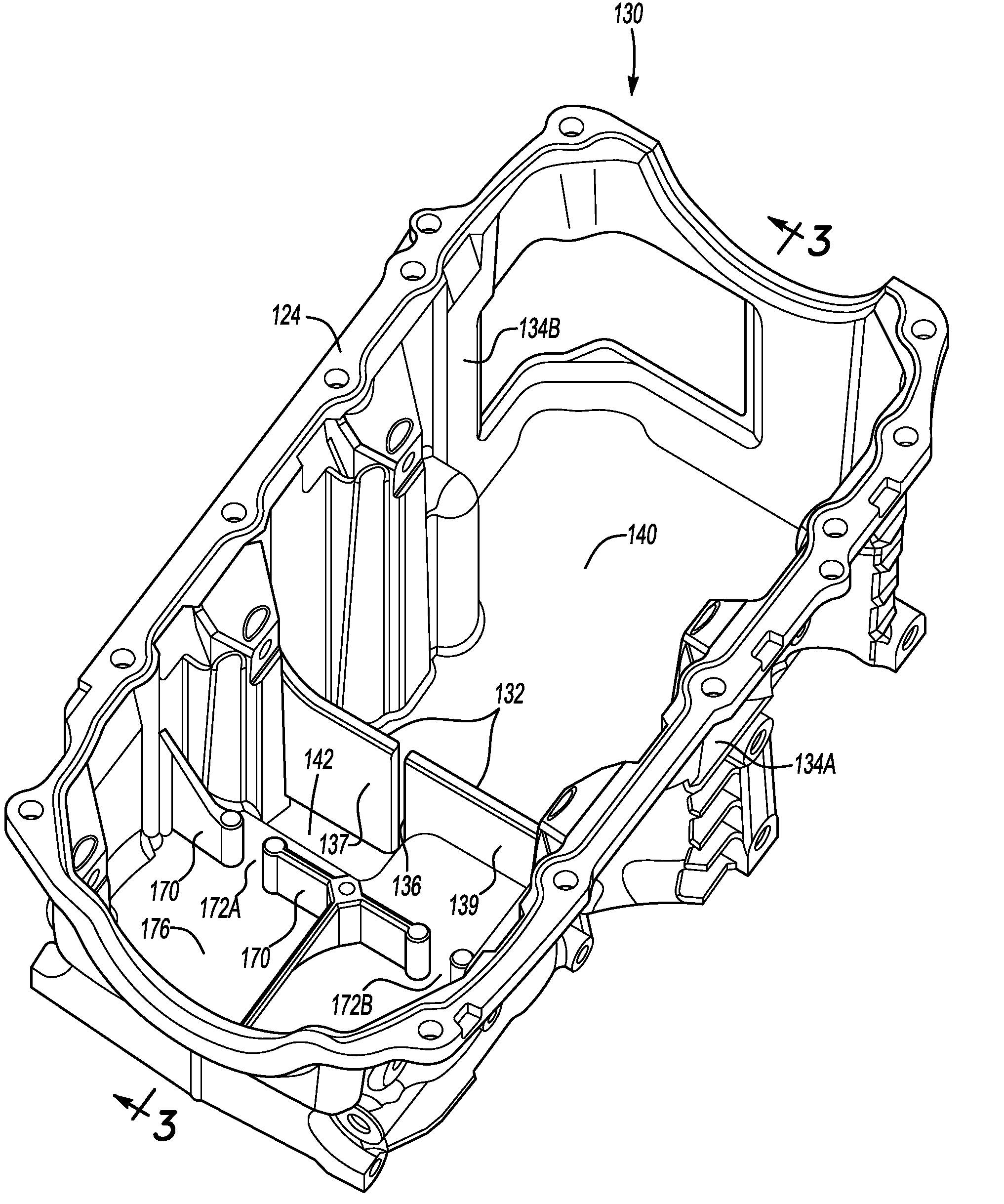
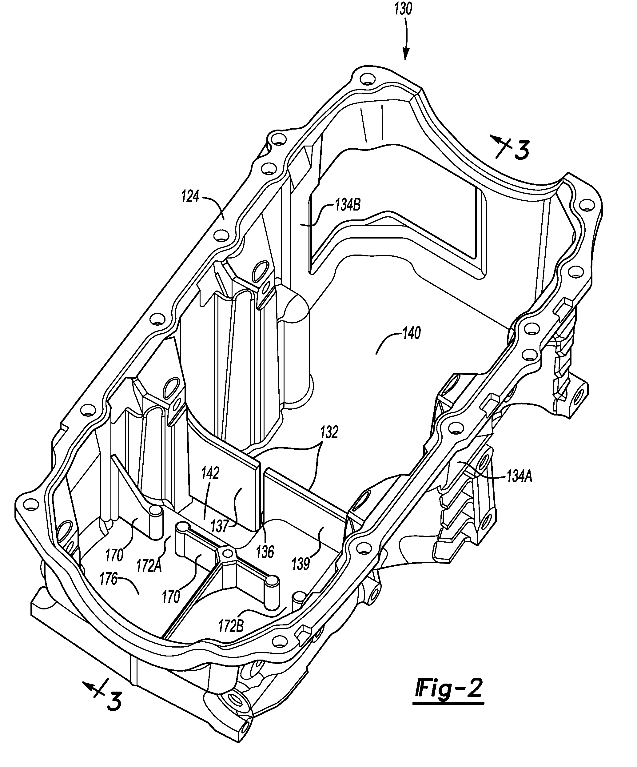
[0015]The engine 12 includes an engine block 22 to which an oil pan 24 is mounted. The engine block 22 supports a crankshaft 26 which rotates about an axis of rotation 28, as is known. The oil pan 24 is mounted to the engine block 22 generally below the crankshaft 26. The oil pan 24 is a cast aluminum alloy, but may alternatively be stamped sheet metal, or any other suitably formed material.

[0016]As is typical in rear wheel-drive applications, the engine 12 is tilted with respect to horizontal in order for the transmission 14 to connect with the driveshaft 16. That is, the...


PUM


Abstract

An oil level management system for a vehicle has an oil pan configured to contain oil and to be mountable to an engine block with a baffle extending transverse to the axis of rotation of the engine crankshaft when the oil pan is so mounted. The baffle is configured to partially define a first oil reservoir and a second oil reservoir, as well as an oil flow opening such that the oil reservoirs are in fluid communication with one another and are characterized by respective first and second oil levels within the pan. The second reservoir drains to the first reservoir when the engine is running and when the engine block and crankshaft are positioned on the vehicle with the axis of rotation tilted from horizontal. The first oil level is lower than the second oil level to avoid oil contact with the crankshaft.

Description

TECHNICAL FIELD[0001]The invention relates to an engine oil level management system, and specifically to an oil pan that is configured to manage oil level, as well as to a method of assembling engines in vehicles.BACKGROUND OF THE INVENTION[0002]A vehicle engine typically includes an oil pan that is mounted to the engine block. Oil is used to lubricate and cool the moving parts of the engine, including the crankshaft. The oil drains from the engine block into and collects in the oil pan before being pumped from the oil pan and recirculated through the engine again. If the moving parts contact the oil collected in the oil pan, the oil pressure decreases while the oil temperature increases, reducing oil life. Additionally, the oil becomes aerated, and is less efficient at cooling the engine. The oil contact also contributes to spin losses, reducing engine power.[0003]In a front wheel-drive vehicle, the engine is typically installed with the axis of rotation of the crankshaft generally...

Claims


Application Information

Patent Timeline
Patent Type & Authority Applications(United States)
IPC IPC(8): F01M7/00F01M11/00
CPCF01M2011/0041F01M11/0004
Inventor RIEDEL, PAULO A.PANNU, MANMEET S.FULTON, KENDELL
Owner GM GLOBAL TECH OPERATIONS LLC
Why Eureka
Try Eureka