Apparatus and Method for Replacing an Oil Pressure Regulating Assembly and a High Pressure Relief Valve Assembly

a technology of oil pressure regulating assembly and high pressure relief valve, which is applied in the direction of machines/engines, manufacturing tools, other domestic articles, etc., can solve the problems of oil pressure up past the minimum specification, lubricating system lacking the capacity to absorb increased oil flow demands, and heavy-duty engines such as truck engines can experience low oil pressure. , to achieve the effect of reducing variability and increasing oil pressur

Active Publication Date: 2013-04-25
CATERPILLAR INC
View PDF1 Cites 5 Cited by
  • Summary
  • Abstract
  • Description
  • Claims
  • Application Information

AI Technical Summary

Benefits of technology

[0004]A less expensive solution to the problem of low oil pressure has been developed in which a kit is provided to replace the original oil pressure regulator spring (“main spring”) with a new main spring and to replace the original high pressure relief spring (“peak clipping spring”) with a new peak clipping spring. The new main spring is stiffer than the original main spring to increase oil pressure without over-pressuring the filter or lubricating system. The new main spring may be made from a different material to minimize or limit variability in oil pressure.

Problems solved by technology

Heavy duty engines such as truck engines can experience low oil pressure, especially near the end of the engine service life.
This low pressure is the result of the lubricating system lacking the capacity to absorb increased oil flow demands created by normal engine wear over the life of the engine.
Replacing the engine block and / or crankshaft can bring the oil pressure up past the minimum specification, but is very expensive.

Method used


Image

  • Apparatus and Method for Replacing an Oil Pressure Regulating Assembly and a High Pressure Relief Valve Assembly
  • Apparatus and Method for Replacing an Oil Pressure Regulating Assembly and a High Pressure Relief Valve Assembly
  • Apparatus and Method for Replacing an Oil Pressure Regulating Assembly and a High Pressure Relief Valve Assembly

Examples


example

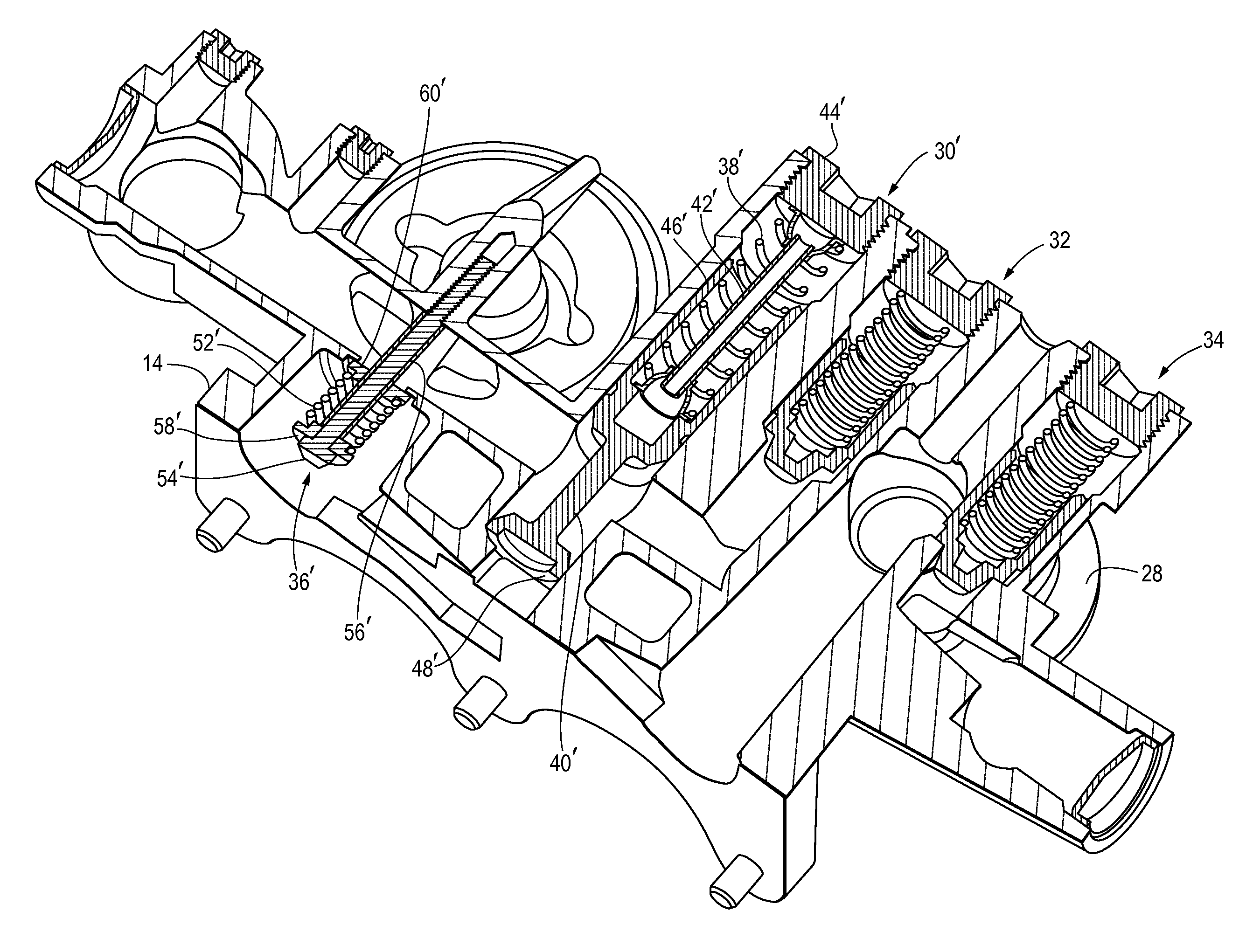
[0042]Table B shows the increase in oil pressure achieved after replacing the old (original) main spring 38 and peak clipping spring 52 with a replacement main spring 38′ and a replacement peak clipping spring 52′. When the engine is operating, either before or after replacement of the springs 38, 52, the oil pressure tends to rise rapidly until about 1300 RPM before leveling off. Replacing the springs 38, 52 resulted in an increase in oil pressure throughout almost the entire range of engine speeds, with the largest increases (of over 10%) occurring in the range of about 900-1800 RPM. For example, at 900 RPM (low idle) the oil pressure was raised to 24 psi from 19 psi.

TABLE BEngineOil Pressure WithOil Pressure% SpeedReplacementWith OldIncrease in(RPM)Springs (psi)Springs (psi) Oil Pressure7001618−12.50800201810.00900241920.831000282221.431300363016.671500373213.511700393510.261800403610.00200041394.88


PUM

PropertyMeasurementUnit
diameteraaaaaaaaaa
heightaaaaaaaaaa
heightaaaaaaaaaa

Abstract

A method of increasing oil pressure in a heavy duty truck engine lubricating system is provided. The lubricating system comprises an oil pressure regulating assembly mounted in an oil filter base and having a main spring to regulate oil pressure, and a high pressure relief valve assembly mounted in the oil filter base and having a peak clipping spring to relieve oil pressure when the pressure exceeds a specified limit. The method includes the steps of replacing the main spring with a replacement main spring having a higher spring constant and replacing the peak clipping spring with a replacement peak clipping spring having a higher spring constant. A replacement kit for increasing oil pressure is also provided.

Description

TECHNICAL FIELD[0001]This disclosure relates generally to lubricating systems for internal combustion engines. More particularly, this disclosure relates to an apparatus and method for replacing the oil pressure regulating assembly and high pressure relief assembly in a lubricating system used in heavy duty vehicles in order to increase oil pressure to within a specified range.BACKGROUND[0002]Internal combustion engines require lubricating systems to lubricate moving parts and to remove heat. In large internal combustion engines for use in heavy duty vehicles, an oil pump distributes oil throughout the engine and through an oil filter mounted on a filter base. The filter base may be equipped with an oil pressure regulating assembly and high pressure relief assembly.[0003]Heavy duty engines such as truck engines can experience low oil pressure, especially near the end of the engine service life. This low pressure is the result of the lubricating system lacking the capacity to absorb ...

Claims


Application Information

Patent Timeline
Patent Type & Authority Applications(United States)
IPC IPC(8): B23P6/00B23P17/00
CPCF01M1/16F01M2001/1085F01M2001/1092B23P6/00F01L1/462Y10T29/49233A61K9/2866Y10T29/49716Y10T29/4973Y10T29/53613Y10T29/49611A61K9/284
Inventor OSTEIN, ADAM WILLIAMBACH, CHRISTOPHER LEESAVAGE, JR., PATRICK W.GRAHAM, CURTIS JOHN
Owner CATERPILLAR INC
Why Eureka
Try Eureka