Piston for an internal combustion engine

A technology for internal combustion engines and pistons, applied in the field of internal combustion engine pistons, to achieve the effect of reducing friction

Inactive Publication Date: 2013-11-20
MAHLE INT GMBH
View PDF8 Cites 6 Cited by
  • Summary
  • Abstract
  • Description
  • Claims
  • Application Information

AI Technical Summary

Problems solved by technology

Although lubricating oil from the crankcase acts on the bottom edge of the piston skirt; however, it is only possible to provide lubricating oil to the less highly loaded lower area

Method used


Image

  • Piston for an internal combustion engine
  • Piston for an internal combustion engine
  • Piston for an internal combustion engine

Examples


Embodiment Construction

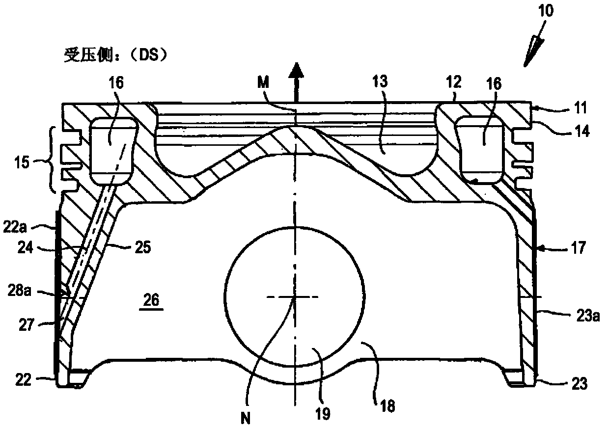
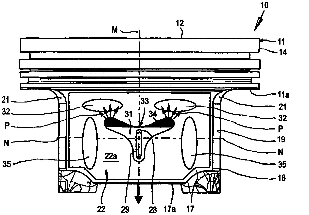
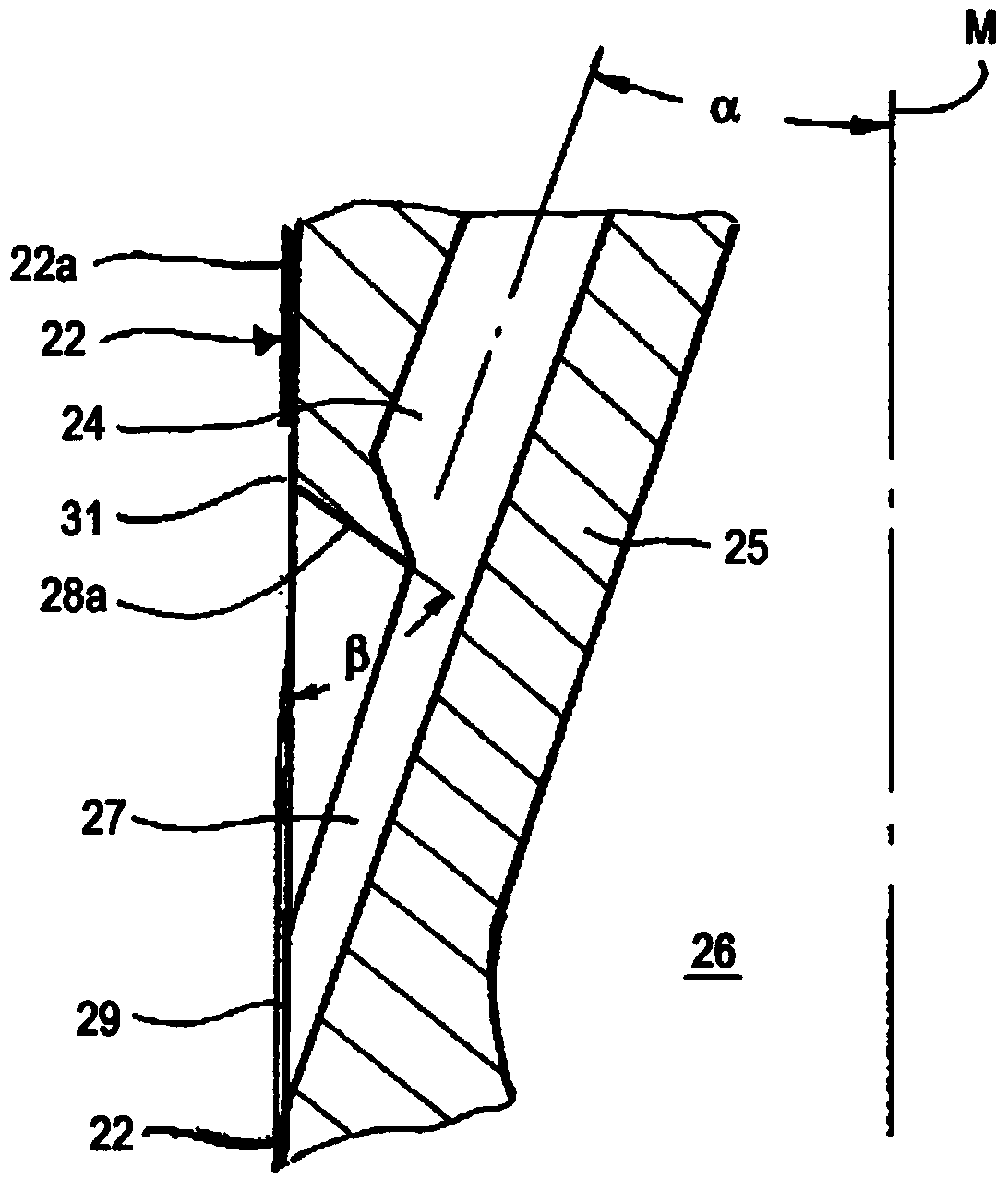
[0028] Figures 1 to 3 A first embodiment of a piston 10 according to the invention is shown. Piston 10 may be a one-piece piston or a piston consisting of several parts. Piston 10 can be made of steel and / or light metal material. Figures 1 to 3 A one-piece box piston 10 is shown as an example. The piston 10 has a piston head 11 with a piston crown 12 , a surrounding crown land 14 and a piston ring section 15 for receiving piston rings (not shown), the piston crown having a crown recess 13 . A circumferential cooling channel 16 is provided at the level of the piston ring part 15 . Furthermore, the piston 10 has a piston skirt 17 with a pin hub 18 and a hub bore 19 for receiving a piston pin (not shown). The pin boss 18 is connected to the underside 11 a of the piston head 11 via a pin boss connection 21 . The pin hubs 17 are connected to each other via working faces 22 , 23 . In this case the working surface 22 corresponds to the pressure side DS of the piston 10 and th...


PUM

PropertyMeasurementUnit
Depthaaaaaaaaaa

Abstract

A piston for an internal combustion engine has a piston head and a piston skirt. The piston head has a circumferential ring belt and a circumferential cooling channel. The piston skirt has a working surface assigned to its major thrust side and to its minor thrust side. A bore that proceeds from the cooling channel is provided, which ends in the working surface assigned to the major thrust side, and is disposed at an incline, in such a manner that the bore exit encloses an acute angle (α) with the center axis (M) of the piston. An opening is formed in the working surface, and a deflection surface inclined relative to the working surface is provided between the bore and the bore exit. The working surface assigned to the major thrust side has a depression which forms at least one oil capture region above the opening.

Description

technical field [0001] The invention relates to a piston for an internal combustion engine with a piston head and a piston skirt, wherein the piston head has a circumferential piston ring and a circumferential cooling channel in the region of the piston ring, the piston skirt has a pressure side with it and a skirt with it. The working surface corresponding to the pressing side. Background technique [0002] In modern internal combustion engines it is very difficult to ensure an optimal lubricant supply to the working surfaces. This is not only related to the upward stroke but also to the downward stroke. During the upward stroke, the working surface corresponding to the back pressure side of the piston is in close contact with the corresponding cylinder working surface. The working surface rests against the corresponding cylinder working surface. It is therefore very important to provide sufficient lubricant on the downstroke, since in this case a maximum frictional force...

Claims


Application Information

Patent Timeline
IPC IPC(8): F16J1/08F01M1/06
CPCF16J1/08F02F3/22
Inventor 赖纳·沙普
Owner MAHLE INT GMBH
Why Eureka
Try Eureka