Vehicle braking apparatus suppressing excessive slip of wheel during braking

a technology of braking apparatus and cylinder, which is applied in the direction of braking system, shock absorber, instruments, etc., can solve the problem of limit to the increase in braking power, and achieve the effect of increasing the braking oil pressure supplied to the wheel cylinder to achieve maximum braking performan

Inactive Publication Date: 2011-07-28
TOYOTA JIDOSHA KK
View PDF26 Cites 5 Cited by
  • Summary
  • Abstract
  • Description
  • Claims
  • Application Information

AI Technical Summary

Benefits of technology

[0022]As described above, during the vehicle braking, the climb rate of the wheel cylinder braking oil pressure is set smaller than the climb rate corresponding to the climb rate of the master cylinder oil pressure from the time point at which the braking oil pressure of the wheel cylinder reaches the predetermined threshold value. Therefore, during the vehicle braking, while the wheel cylinder braking oil pressure started up according to the master cylinder oil pressure, the braking is suppressed within a range where the excessive wheel slip or the increase of the braking distance is not generated, so that the vehicle braking can be optimized to maximally enhance the braking performance.
[0023]The braking oil pressure supplied to the wheel cylinder is increased, and a brake pad that is normally separated from a brake disc is driven and pressed against the brake disc, thereby performing the wheel braking. Therefore, in driving the brake pad, it is necessary to generate a flow of the brake oil in order to move the brake pad to eliminate a clearance for releasing the braking between the brake disc and the brake pad. Hereinafter, an integrating amount of the flow of the brake oil is referred to as “brake oil consumption amount”. During the wheel braking, when the threshold value relating to the wheel cylinder braking oil pressure is the wheel cylinder braking oil pressure at which an increment of the wheel cylinder braking oil pressure and an increment of the brake oil consumption amount are started to be proportional to each other, the time point at which the wheel cylinder braking oil pressure reaches the threshold value becomes the proper timing in which the braking is optimized by adjustment of the braking power.
[0024]That the wheel cylinder braking oil pressure reaches the threshold value may directly be detected by providing an oil pressure sensor near the wheel cylinder. However, in the present vehicle power assist braking apparatus, a high-performance master cylinder oil pressure sensor is provided to actuate power assist means based on the master cylinder oil pressure. Therefore, when the wheel cylinder braking oil pressure estimates that the wheel cylinder braking oil pressure reaches the threshold value based on the master cylinder oil pressure, the threshold value can adequately be recognized without newly providing a sensor for detecting the threshold value.
[0025]At this point, it is assumed that tm1 is a time point at which the master cylinder oil pressure reaches a predetermined first pressure in an braking initial stage in which the brake oil consumption amount is substantially proportional to the wheel cylinder braking oil pressure, it is assumed that tm3 is a time point at which the master cylinder oil pressure reaches an oil pressure at which the increment of the brake oil consumption amount is started to be substantially proportional to the increment of the wheel cylinder braking oil pressure, and it is assumed that tm2 is a time point at which the master cylinder oil pressure reaches an oil pressure at a boundary between a wheel cylinder braking oil pressure-brake oil consumption amount relationship in which the brake oil consumption amount is substantially proportional to the wheel cylinder braking oil pressure and a wheel cylinder braking oil pressure-brake oil consumption amount relationship in which the increment of the brake oil consumption amount is substantially proportional to the increment of the wheel cylinder braking oil pressure. When a time point at which a time corresponding to a value in which (tm2−tm1) is multiplied by the predetermined first factor and a time corresponding to a value in which (tm3−tm2) is multiplied by the predetermined second factor elapsed from the time point tm1 is estimated to be the time point at which the wheel cylinder braking oil pressure reaches the threshold value, the delay of the increase of the wheel cylinder oil pressure with respect to the increase of the master cylinder oil pressure is adequately estimated based on a characteristic of the relationship between the wheel cylinder oil pressure and the brake oil consumption amount, and the sudden braking can be optimized.
[0026]Alternatively, when the wheel cylinder braking oil pressure sensor is provided, obviously that the wheel cylinder braking oil pressure reaches the threshold value can be estimated by directly detecting the wheel cylinder braking oil pressure.
[0027]When the sudden braking is being performed to the vehicle in a degree of urgency that is not lower than a predetermined degree of urgency, the climb rate of the wheel cylinder braking oil pressure is set smaller than the climb rate corresponding to the climb rate of the master cylinder oil pressure from the time point at which the braking oil pressure of the wheel cylinder reaches a predetermined threshold value. Therefore, the optimum actuation of the braking apparatus can be secured when the sudden braking is performed to the vehicle to possibly push the braking into the braking that is largely out of the optimum actuation. The determination of the degree of urgency of the vehicle braking is made by the climb rate of the master cylinder oil pressure when that the wheel cylinder braking oil pressure reaches the threshold value is estimated based on the master cylinder oil pressure. The determination of the degree of urgency of the vehicle braking is made by the climb rate of the wheel cylinder braking oil pressure when that the wheel cylinder braking oil pressure reaches the threshold value is estimated by directly detecting the wheel cylinder braking oil pressure. Therefore, the degree of sudden braking required for the vehicle by the driver can adequately be recognized to execute the braking control in a process of chasing whether the wheel cylinder braking oil pressure reaches the threshold value.

Problems solved by technology

Although the braking power that can be obtained by the front wheel is increased, there is a limitation to the increase in braking power caused by the increase in vertical load.

Method used


Image

  • Vehicle braking apparatus suppressing excessive slip of wheel during braking
  • Vehicle braking apparatus suppressing excessive slip of wheel during braking
  • Vehicle braking apparatus suppressing excessive slip of wheel during braking

Examples


first embodiment

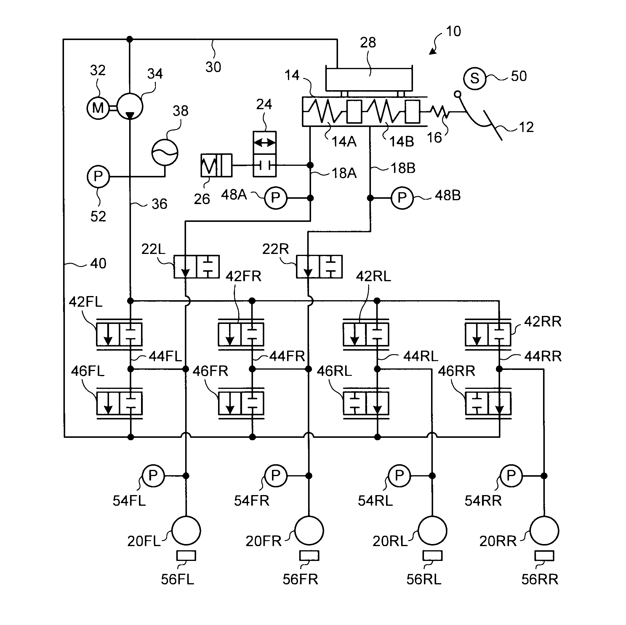
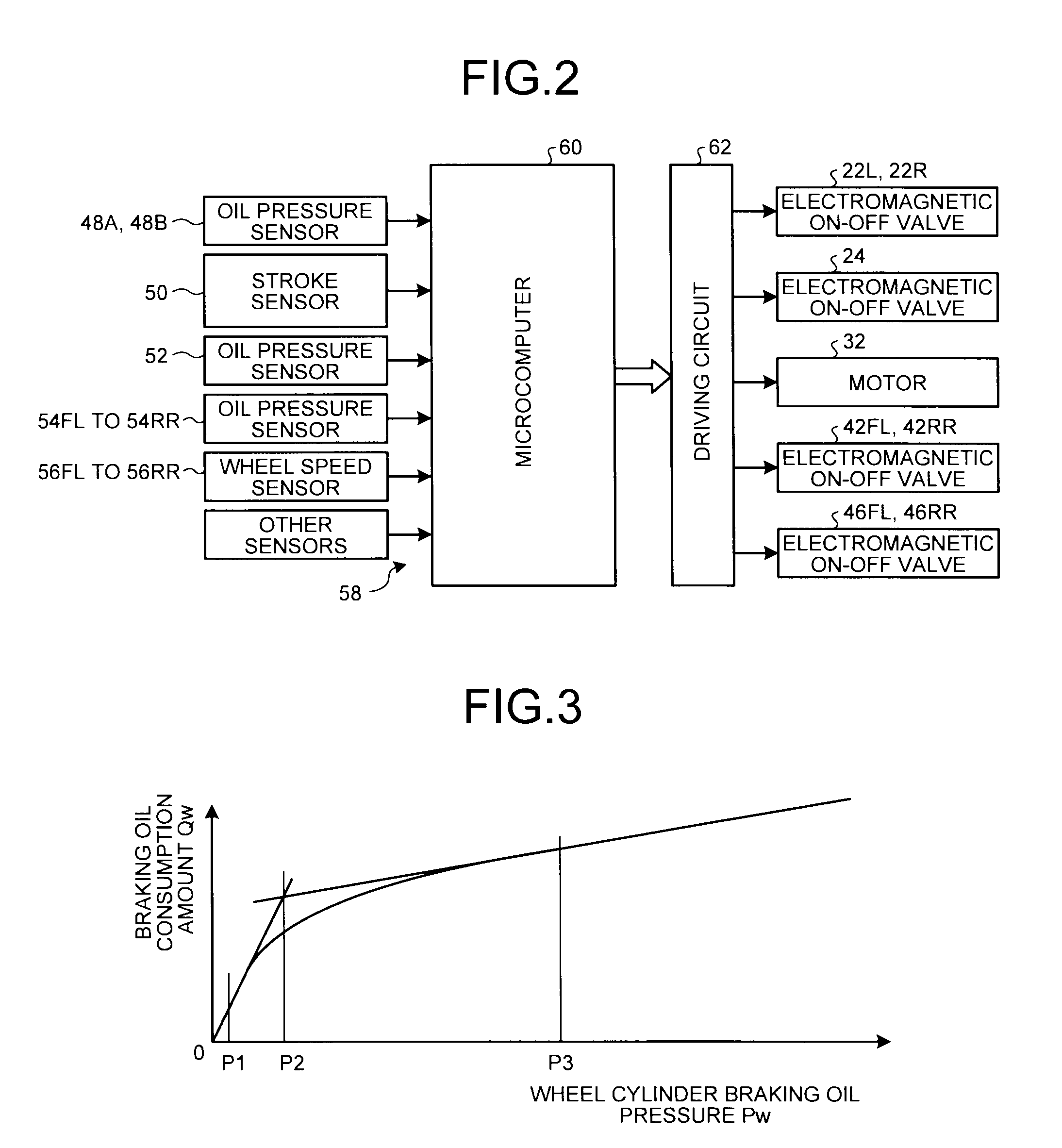
[0071]A first embodiment of the present invention will be described below. FIG. 1 is an oil pressure circuit diagram illustrating an example of a vehicle braking apparatus according to a first embodiment of the present invention. FIG. 2 is a view illustrating an example of an electronic control unit included in the vehicle braking apparatus of the first embodiment. Because the present invention mainly focuses on a software configuration relating to actuation of the vehicle braking apparatus, the hardware configuration illustrated in FIG. 1 and FIG. 2 is well known. A braking apparatus 10 wholly illustrated includes a master cylinder 14 that pumps braking operating oil in response to a stepping-on operation of a brake pedal 12 by a driver. A dry stroke simulator 16 is provided between the brake pedal 12 and the master cylinder 14.

[0072]As illustrated in FIG. 1, the master cylinder 14 includes a first master cylinder chamber 14A and a second master cylinder chamber 14B, one end of a l...

second embodiment

[0095]A second embodiment of the present invention will be described below. A vehicle braking apparatus according to a second embodiment of the present invention differs from the vehicle braking apparatus of the first embodiment in that the control is performed such that the climb rate of the wheel cylinder braking oil pressure corresponding to the front wheel is decreased smaller than the climb rate corresponding to the climb rate of the master cylinder oil pressure, that is, a pitching suppression control (reduction control of the first embodiment) is executed when one of two different pitching suppression control execution conditions is satisfied. Hereinafter, the pitching suppression controls executed in the different pitching suppression control execution conditions are referred to as a first pitching suppression control and second pitching suppression control. Because the basic configuration of the vehicle braking apparatus of the second embodiment is substantially identical t...

third embodiment

[0109]A third embodiment of the present invention will be described below. A vehicle braking apparatus according to a third embodiment of the present invention differs from the vehicle braking apparatus of the first and second embodiments in that not only the pitching suppression control (including the case in which the pitching suppression control execution conditions differs from each other like the second embodiment) but also a brake assist control and a right and left distribution control can be executed. Because the basic configuration of the vehicle braking apparatus of the third embodiment is substantially identical to that of the vehicle braking apparatus of the first embodiment, the description is omitted.

[0110]The pitching suppression control of the third embodiment is similar to that executed by the vehicle braking apparatus of the first embodiment and that executed by the vehicle braking apparatus of the second embodiment. In the pitching suppression control, the climb r...


PUM


Abstract

A vehicle braking apparatus that can exert high braking performance during vehicle braking is implemented by a control mode that can be realized in a braking apparatus. In controlling the braking apparatus of a vehicle, a climb rate of a wheel cylinder braking oil pressure is decreased smaller than a climb rate corresponding to a climb rate of a master cylinder oil pressure from a time point at which the wheel cylinder braking oil pressure reaches a predetermined threshold value. The time point at which the wheel cylinder braking oil pressure reaches the predetermined threshold value is estimated based on the climb process of the master cylinder oil pressure or directly detected.

Description

TECHNICAL FIELD[0001]The present invention relates to a braking apparatus of a vehicle such as an automobile, particularly to a vehicle braking apparatus which suppresses a loss of a braking effect due to excessive slip during sudden braking.BACKGROUND ART[0002]Wheels slip on a road surface when a degree of braking is increased above a certain level during the braking of the vehicle such as an automobile. When the slip is increased, a friction coefficient acting between the wheel and the road surface turns downward after a maximum value. Therefore, when the braking is suddenly performed, a braking distance until the vehicle stops since the braking is started becomes longer rather than a minimum braking distance that can be obtained by optimum braking. When the vehicle is braked, a vertical load of the wheel moves from a rear wheel side to a front wheel side to decrease the vertical load of the rear wheel, and a braking power that can be obtained by the rear wheel is decreased while ...

Claims


Application Information

Patent Timeline
Patent Type & Authority Applications(United States)
IPC IPC(8): B60T8/172
CPCB60T8/3275B60T2201/03B60T8/4081B60T8/17B60T8/176
Inventor KATO, HIDEHISAKAWAMURO, JUNJINARITA, TETSUHIRO
Owner TOYOTA JIDOSHA KK
Why Eureka
Try Eureka