Method and Apparatus for Injecting a Jet of Fluid with a Variable Direction and/or Opening

a technology of variable direction and opening, applied in lighting and heating apparatus, water supply installations, combustion types, etc., can solve the problem of only allowing a fairly small change in the direction of the jet, and achieve the effect of optimizing robust apparatus and great variation in direction and/or apertur

Inactive Publication Date: 2010-02-11
LAIR LIQUIDE SA POUR LETUDE & LEXPLOITATION DES PROCEDES GEORGES CLAUDE
View PDF4 Cites 9 Cited by
  • Summary
  • Abstract
  • Description
  • Claims
  • Application Information

AI Technical Summary

Benefits of technology

[0007]Therefore the invention relates to an apparatus for the injection of a fluid jet resulting from an interaction between a primary jet and at least one secondary jet, said apparatus making it possible to vary the direction and / or the aperture of said resultant jet.
[0014]The invention therefore makes it possible to vary the direction and / or the aperture of the resultant jet by changing the force of at least one secondary jet with said means.
[0015]Preferably, the means for controlling the force of the at least one secondary jet are means making it possible to control the ratio between the force of the secondary jet and the force of the primary jet.
[0016]The invention therefore makes it possible to produce a large variation in the direction and / or aperture of a jet without making use of mechanical means, potential sources of malfunction, in particular in hostile environments, such as high-temperature fire chambers.
[0017]The control means notably allow an active or dynamic control of the force of at least one secondary jet, that is to say they make it possible to vary the force or forces without interrupting the injection of the main jet. The apparatus according to the invention therefore allows a dynamic variation in the direction and / or the aperture of the resultant jet.
[0018]Preferably, the number of secondary jets interacting with the primary jet to obtain the desired effect on the resultant jet will be minimized so as to limit the complexity and the cost of manufacture of the apparatus but also the complexity and the cost of the system for supplying and regulating the flow rates of the fluids if the secondary jets are controlled in an independent manner. For example, a mono-directional effect may be obtained with a single secondary jet.

Problems solved by technology

However, this method, which is limited to atomized jets, allows only a fairly slight change in the direction of the jet.

Method used


Image

  • Method and Apparatus for Injecting a Jet of Fluid with a Variable Direction and/or Opening
  • Method and Apparatus for Injecting a Jet of Fluid with a Variable Direction and/or Opening
  • Method and Apparatus for Injecting a Jet of Fluid with a Variable Direction and/or Opening

Examples


Embodiment Construction

[0023]The various features of the embodiments of the apparatus according to the invention and its use will appear more clearly from the following detailed description, reference being made to the figures which represent, in a schematic manner, exemplary embodiments given as being nonlimiting and more particularly:

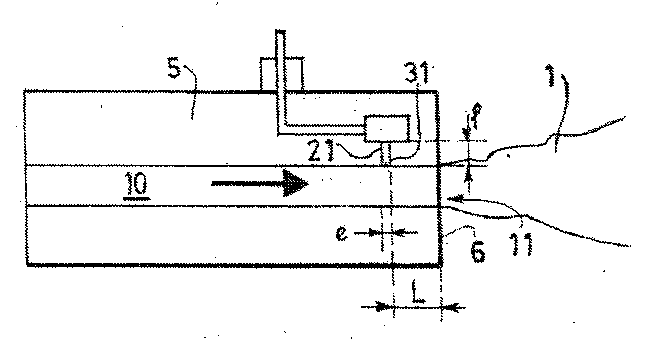
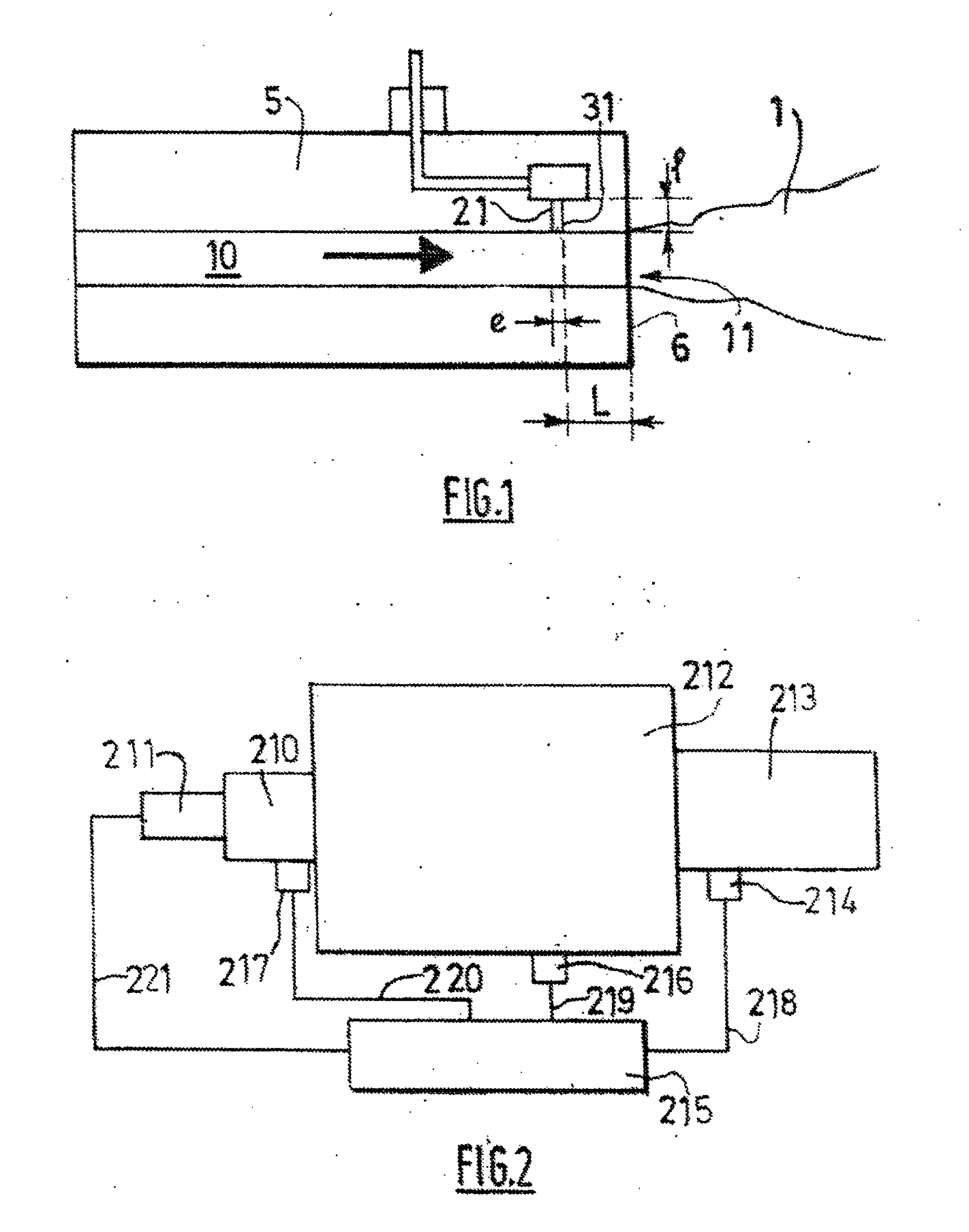
[0024]FIG. 1: diagram of an apparatus according to the invention for the control of a flow by interaction of jets.

[0025]FIG. 2: regulation of an apparatus according to the invention mounted on a fire chamber.

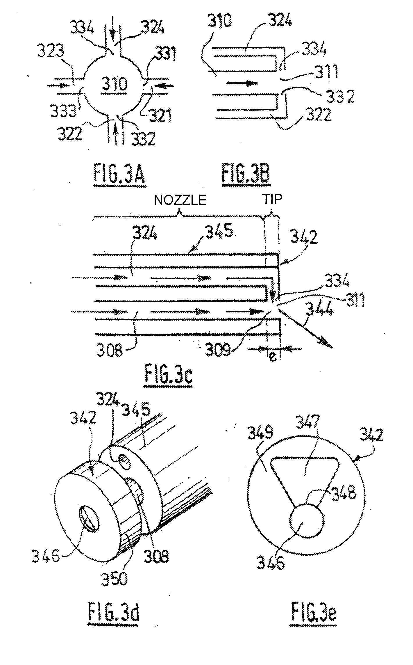
[0026]FIGS. 3A and B: apparatus for the control of the direction of the resultant jet, FIG. 3A being a cross section and FIG. 3B a longitudinal section of an apparatus comprising four secondary jets placed respectively at 90° from one another and coming into incidence perpendicular to the direction of the primary jet.

[0027]FIGS. 3C, D and E: use of a tip to convert a nozzle with parallel primary and secondary jets into an apparatus according to the invention.

[0028]FIGS....


PUM


Abstract

The invention relates to an apparatus for injecting at least one jet of fluid, in which the direction and / or opening of at least one of the jets may be variable, comprising means of injecting at least one main fluid jet, means for injecting at least one secondary fluid jet, and means for causing at least one main fluid jet to interact with at least one secondary fluid jet and producing a fluid jet resulting from this interaction whose direction and / or opening are variable; as well as the associated method; and the uses of these.

Description

[0001]The present invention relates to an injection apparatus making it possible to vary the direction and / or the aperture of a fluid jet, for example a jet of air or of oxygen, of nitrogen, of gaseous fuel or else of liquid or solid fuel with a gas, said fluid jet resulting from an interaction between a primary fluid jet and at least one secondary fluid jet. The invention relates notably to such an injection gun.[0002]The invention also relates to the use of said injection apparatus to vary the direction and / or the aperture of a fluid jet, for example in contact with a surface and notably above a load. It also concerns a method of injection in which the user varies the direction and / or the aperture of at least one fluid jet.BACKGROUND OF THE INVENTION[0003]It is known practice from EP-A-0545357 to change the direction of an atomized jet by means of a control gas flow: (1) by bringing the material to be atomized across an atomization passageway having a portion of constant cross sec...

Claims


Application Information

Patent Timeline
Patent Type & Authority Applications(United States)
IPC IPC(8): A23G9/28F23D99/00
CPCF23D14/84Y10T137/0318Y10T137/87571
Inventor LABEGORRE, BERNARDDOCQUIER, NICOLASZAMUNER, BERNARDLEDERLIN, THOMASPOINSOT, THIERRYFAIVRE, VINCENT
Owner LAIR LIQUIDE SA POUR LETUDE & LEXPLOITATION DES PROCEDES GEORGES CLAUDE
Why Eureka
Try Eureka