
De-Fouling Tubes for Cooling Tower

a technology of cooling tower and tube assembly, which is applied in the direction of combustible gas purification/modification, lighting and heating apparatus, and separation processes, etc., can solve the problems of increasing the resistance to heat transfer across the tube, e.g. magnesium oxide layer may form on the outer surface of the tube assembly, etc., and achieve the effect of increasing the performance of the cooling tower incorporating the tub

Inactive Publication Date: 2010-02-11
LIN SUI MING
View PDF17 Cites 5 Cited by
  • Summary
  • Abstract
  • Description
  • Claims
  • Application Information

AI Technical Summary

Benefits of technology

The technical effect of this patent is to improve the efficiency of cooling towers by adding a non-sticking layer on the inside of pipes used for water circulation. This helps prevent fouling or buildup of material which could otherwise reduce the flow rate of liquid through the system.

Problems solved by technology

The technical problem addressed in this patent text is the fouling (e.g., magnesium oxide) layer that can form on the outer surface of tubes in air cooling systems, which can reduce heat transfer efficiency and increase resistance to heat transfer. Current solutions such as periodic disassembly and cleaning of the tubes can lead to increased labor, pumping, and maintenance costs. Thus, there is a need for an improved solution to remove the fouling layers.

Method used


Image

  • De-Fouling Tubes for Cooling Tower
  • De-Fouling Tubes for Cooling Tower
  • De-Fouling Tubes for Cooling Tower

Examples


Embodiment Construction

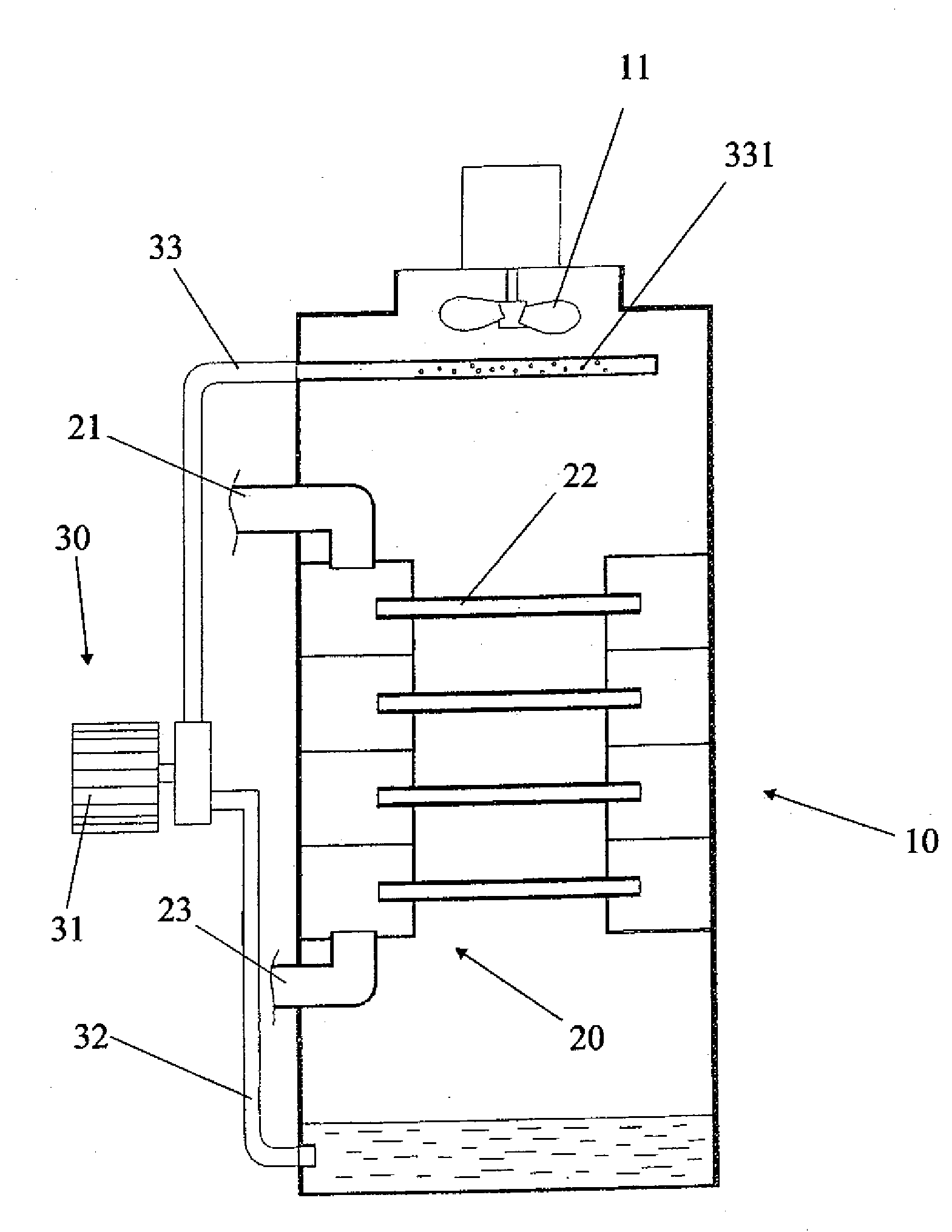
[0022]Referring to FIG. 1, a cooling tower in accordance with the invention is shown. The cooling tower comprises the following components as discussed in detail below.

[0023]A tower structure 10 comprises a collection basin 13 on the bottom, a lower air inlet 12 just above the collection basin 13 for introducing dry air into the tower structure 10, and a top fan 11 for inducing draft in order to draw moist, warm air out of the tower structure 10.

[0024]A clean water circulating assembly 30 comprises a motor driven circulating pump 311 a distribution pipe 33 extending from the circulating pump 31 into an upper portion of the tower structure 10, the distribution pipe 33 having a spraying section 331 with a plurality of orifices just below the fan 11, and a drain pipe 32 in fluid communication between the circulating pump 31 and the collection basin 13.

[0025]A fluid cooling loop 20 comprises an upper hot water inlet pipe 21 below the spraying section 331 for flowing a source of liquid (...


PUM

PropertyMeasurementUnit
Electrical conductoraaaaaaaaaa

Abstract

A tube in one embodiment is formed with a non-stick coating on its inner outer surface. Preferably, the non-stick coating is fluoropolymer. More preferably the fluoropolymer is PTFE. Another non-stick coating is formed on an inner surface of the tube in another embodiment. The non-stick coating served as a de-fouling layer is capable of preventing impurities in the water flowing through the tubes from precipitating thereonto. Hence, the performance of a cooling tower incorporating the tubes can be increased significantly.

Description


Claims


Application Information

Patent Timeline
Owner LIN SUI MING
Learn More