[0029]Reference will now be made in detail to various embodiments of the present invention(s), examples of which are illustrated in the accompanying drawings and described below. While the invention(s) will be described in conjunction with exemplary embodiments, it will be understood that present description is not intended to limit the invention(s) to those exemplary embodiments. On the contrary, the invention(s) is/are intended to cover not only the exemplary embodiments, but also various alternatives, modifications, equivalents and other embodiments, which may be included within the spirit and scope of the invention as defined by the appended claims.
[0030]FIG. 3 is a schematic diagram of a suspension system for vehicles provided with an active roll control system according to various embodiments of the present invention; and FIG. 4 is a cross-sectional view of a pulley unit applied to active roll control system according to various embodiments of the present invention.
[0031]A suspension system for vehicles provided with an active roll control system according to various embodiments of the present invention, as shown in FIG. 3, includes a chassis spring 1 relieving impact from a road and mounted between a vehicle body and an axle, a shock absorber 3 reducing free vibration of the chassis spring 1 and improving ride comfort, and a stabilizer bar 5 suppressing roll of a vehicle.
[0032]The active roll control system 10 applied to the suspension system for vehicles is disposed between a lower arm 7 disposed at both sides of the vehicle body and both ends of the stabilizer bar 5 which is connected to the lower arm 7 by a stabilizer link 50 and actively improves roll of a vehicle by changing torsional rigidity of the stabilizer bar 5 according to a driving condition of the vehicle.
[0033]That is, according to the active roll control system 10, pulley units 20 are provided respectively at lower arms 7 disposed at both sides of the vehicle body. The pulley unit 20 controls rotation of a wire pulley 25 by using torque of a worm 21 (referring to FIG. 4) of driving device operating by a motor and a worm wheel 23 of driven device.
[0034]In addition, one end of a wire 30 is wound on the wire pulley 25 of the pulley unit 20 through a hole 55 formed in the housing 27, and the other end of the wire 30 is connected to respective end of the stabilizer bar 5 through a mounter 31.
[0035]The pulley unit 20 includes a housing 27, and the housings 27 are fixedly mounted on both lower arms 7, as shown in FIG. 4.
[0036]An electric motor 29 rotating clockwise or anticlockwise according to a control signal of a controller 40 is fixedly mounted at one end of the housing 27.
[0037]In addition, the worm 21 of the driving device integrally connected to a rotation shaft 33 of the electric motor 29 is provided at a lower portion in the housing 27, and the worm wheel 23 of the driven device is rotatably mounted in the housing 27 in a state of being engaged to the worm 21.
[0038]Herein, one end of the worm 21 is integrally connected to the rotation shaft 31 of the electric motor 29, and the other end of the worm 21 is rotatably supported to the housing 27 by a bearing 35.
[0039]The wire pulley 25 is mounted coaxially with the worm wheel 23 of the driven device in the housing 27. Therefore, in a case that the worm wheel 23 rotates, the wire pulley 25 rotates together with the worm wheel 23, and winds or unwinds the wire 30.
[0040]According to the active roll control system 10, the wire 30 is wound on or is unwound from the wire pulley 25 according to an operation of the electric motor 29. Therefore, tension of the wire 30 is changed. Accordingly, the other end of the wire 30 connected to the stabilizer bar 5 through the mounter 31 changes the torsional rigidity of the stabilizer bar 5 and actively improves the roll of the vehicle.
[0041]Herein, one end of the worm 21 is integrally connected to the rotation shaft 31 of the electric motor 29, and the other end of the worm 21 is rotatably supported to the housing 27 by the bearing 35.
[0042]According to various embodiments of the present invention, the worm 21 is used as the driving device, and the worm wheel 23 is used as the driven device. However, a rack and a pinion may be used respectively as the driving device and driven device instead of the worm 21 and the worm wheel 23. It is possible that a linear motor is used as an actuator in order to use the rack as the driving device. The wire 30 may be attached to an wire pulley formed to the pinion and the rack meshed with the pinion may be actuated by the linear motor.
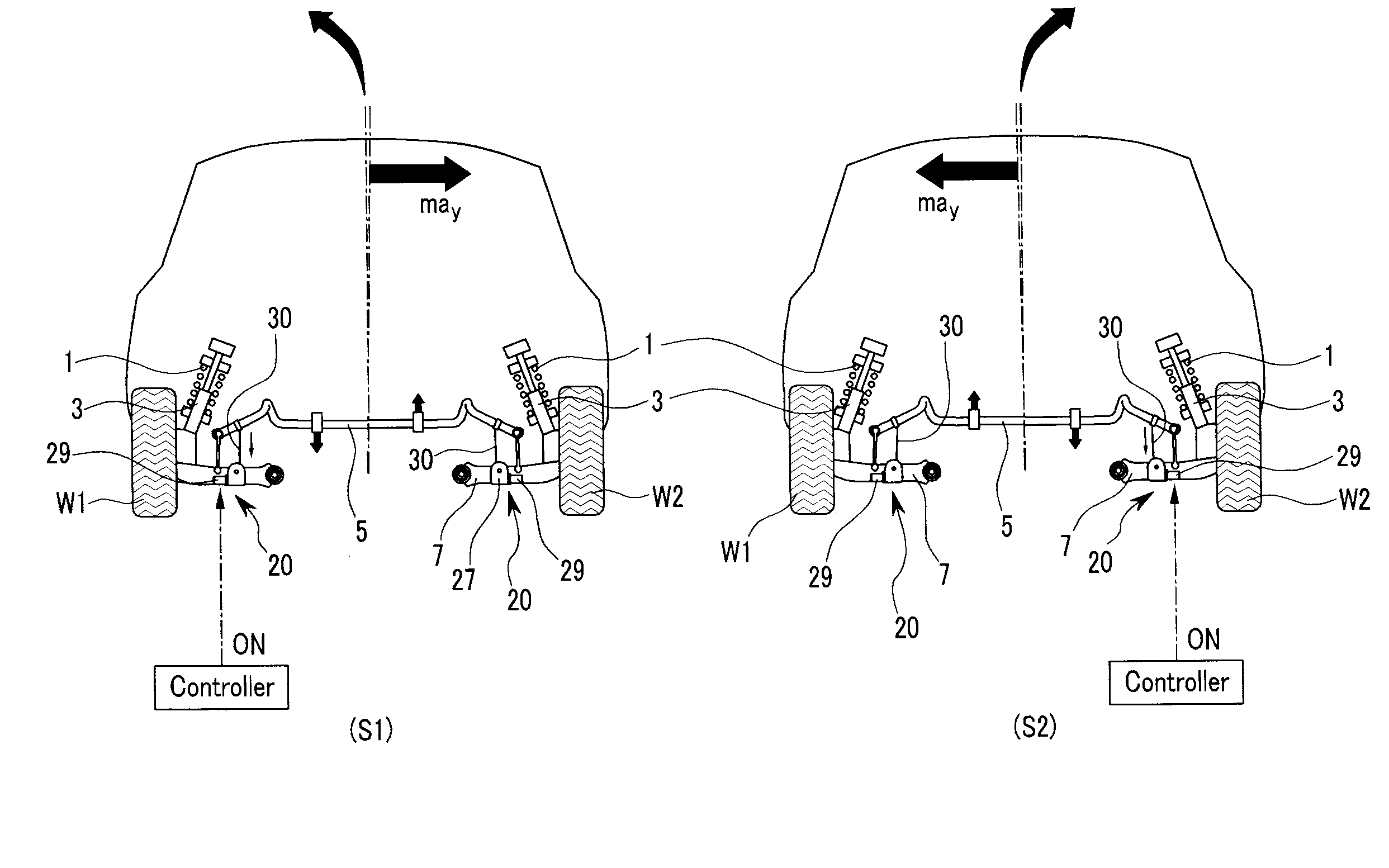
[0043]An operation of the active roll control system 10 is described in detail, referring to FIG. 5.
[0044]In a case that the vehicle turns to the left, the controller 40 controls the left electric motor 29 such that the left wire 30 is wound as shown in S1 of the FIG. 5 based on signals output from an acceleration sensor 41, a vehicle height sensor 43, and a steering sensor 45. In this case, the left end of the stabilizer bar 5 near the left wheel W1 is pulled downwardly, and the torsional rigidity of the left side of the stabilizer bar 5 is strengthened. Therefore, the roll of the vehicle is suppressed.
[0045]In a case that the vehicle, on the contrary, turns to the right, the controller 40 controls the right electric motor 29 such that the right wire 30 is wound as shown in S2 of the FIG. 5 based on the signals output from the acceleration sensor 41, the vehicle height sensor 43, and the steering sensor 45. In this case, the right end of the stabilizer bar 5 near the right wheel W2 is pulled downwardly, and the torsional rigidity of the right side of the stabilizer bar 5 is strengthened. Therefore, the roll of the vehicle is suppressed.
[0046]Since the pulley units 20 are disposed on both lower arms 7 so as to wind or unwind each wire 30 connected to both sides of the stabilizer bar 5 according to the exemplary active roll control system 10 of the present invention, control of the actuator is simplified compared with an active roll control system of hydraulic pressure type. In addition, since complex hydraulic pressure supply system is not applied to the active roll control system 10, layout thereof is very simple.
[0047]In other embodiments of the present invention, the pulley units 20 may be disposed on both ends of the stabilizer bar 5 and the wire 30 may be connected to both ends of the lower arms 7.
[0048]Since connecting positions of the actuator and the stabilizer bar 5 can be controlled, the actuator of one type may be used irrespective of vehicle types.
[0049]An active roll control system according to various embodiments of the present invention can actively control roll of a vehicle by changing torsional rigidity of a stabilizer bar. In addition, control of an actuator may be simplified compared with an active roll control system of hydraulic pressure type. Further, since a hydraulic pressure supply system for supplying or controlling hydraulic pressure including hydraulic pressure pumps, hydraulic pressure valves, and hydraulic lines is not used, layout is very simple.
[0050]For convenience in explanation and accurate definition in the appended claims, the terms “upper” and “lower” are used to describe features of the exemplary embodiments with reference to the positions of such features as displayed in the figures.
[0051]The foregoing descriptions of specific exemplary embodiments of the present invention have been presented for purposes of illustration and description. They are not intended to be exhaustive or to limit the invention to the precise forms disclosed, and obviously many modifications and variations are possible in light of the above teachings. The exemplary embodiments were chosen and described in order to explain certain principles of the invention and their practical application, to thereby enable others skilled in the art to make and utilize various exemplary embodiments of the present invention, as well as various alternatives and modifications thereof. It is intended that the scope of the invention be defined by the Claims appended hereto and their equivalents.