Wind turbine generator

Inactive Publication Date: 2010-02-11
MITSUBISHI HEAVY IND LTD
View PDF13 Cites 37 Cited by
  • Summary
  • Abstract
  • Description
  • Claims
  • Application Information

AI Technical Summary

Benefits of technology

[0022]In particular, by disposing the generator closer to the nacelle relative to the speed-increasing gearbox so that the center of gravity of the drive train is located closer towards the nacelle (i.e., towards the main bearing), the support structure can be reduced in weight by a reduction in moment, whereby the drive train and the nacelle can readily have a lightweight compact structure.
[0023]Since the drive train is attached to the front side or the rear side of the roto

Problems solved by technology

Moreover, as wind turbine generator become larger in size, the drive train component also tend to

Method used


Image

  • Wind turbine generator
  • Wind turbine generator
  • Wind turbine generator

Examples


first embodiment

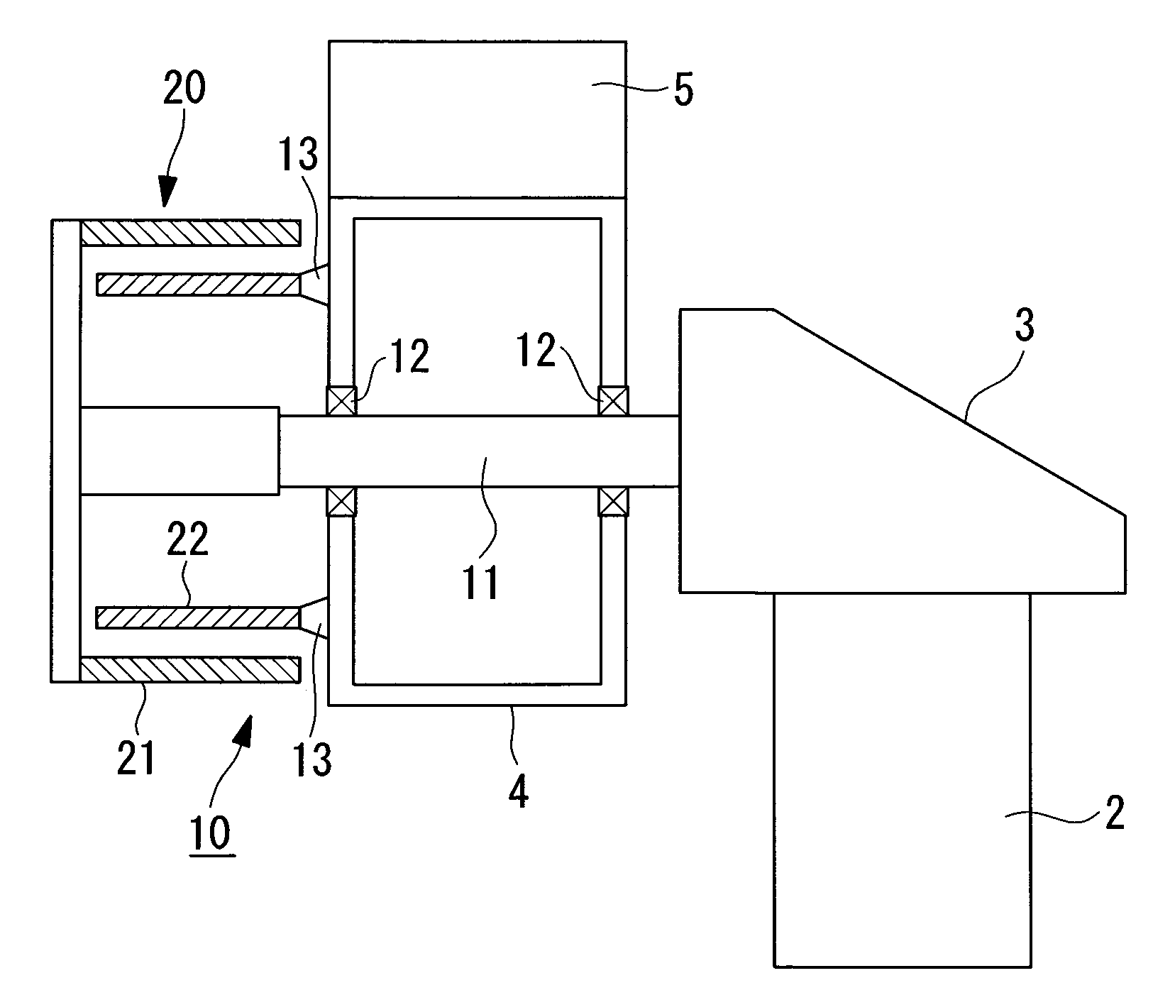
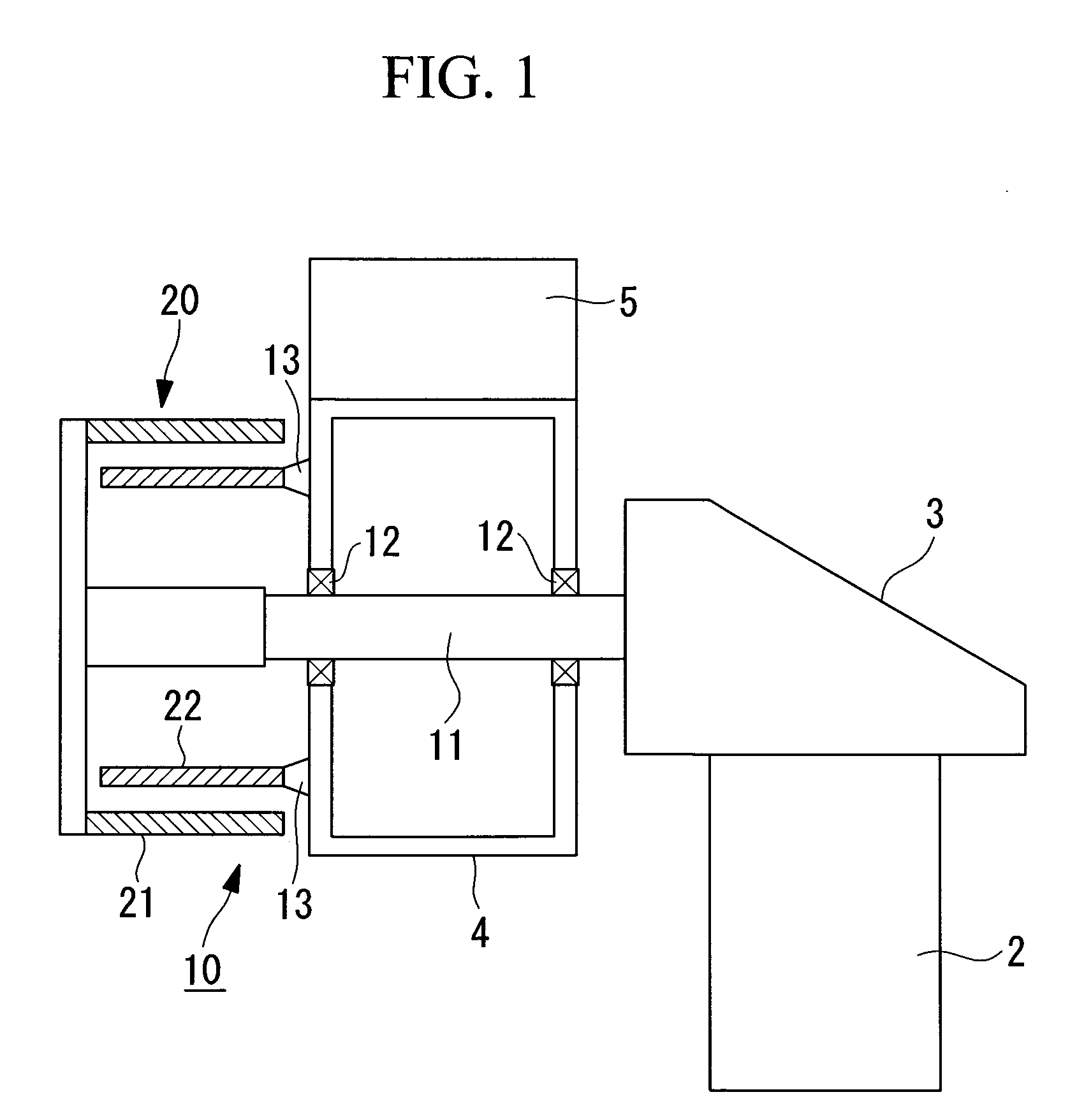
[0065]FIG. 1 is an enlarged cross-sectional view of showing a relevant part of an example of an internal configuration of the rotor head 4 disposed in front of the nacelle 3 and a drive train 10 disposed in front of the rotor head 4 in a state where a rotor-head cover (not shown) is removed. In the embodiment to be described below, the drive train 10 is configured to transmit the rotation of the rotor head 4 directly to a generator 20 without intervention of a speed-increasing gearbox.

[0066]In FIG. 1, the rotor head 4 having the wind-turbine rotor blade 5 is supported by a main shaft 11, which protrudes forward from the nacelle 3, via bearings 12. In other words, when the wind-turbine rotor blade 5 receive wind, the rotor head 4 rotates together with the wind-turbine rotor blade 5 about the main shaft11 securely supported by the nacelle 3.

[0067]A cylindrical stator 21 that constitutes the generator 20 is provided at an end of the main shaft 11 securely supported by the nacelle 3. A ...

second embodiment

[0074]Next, a second embodiment of the wind turbine generator according to the present invention will be described with reference to FIG. 4. Components similar to those in the above embodiment will be given the same reference numerals, and detailed descriptions thereof will be omitted.

[0075]A drive train 10A in this embodiment is equipped with a speed-increasing gearbox 30 between the rotor head 4 and the generator 20 for increasing the speed of rotation of the rotor head 4 and transmitting it to the generator 20. In this case, the speed-increasing gearbox 30 is a single-stage planetary speed-increasing gearbox, and reference numeral 31 in the drawing denotes a sun gear and 32 denotes planet gears.

[0076]In the aforementioned speed-increasing gearbox 30, the sun gear 31, which is rotatably supported by the end of the main shaft 11 via bearings 12, is meshed with the plurality of planet gears 32, which are supported by the front face of the rotor head 4 via a rigid coupling 14, and th...

third embodiment

[0082]Next, a third embodiment of the wind turbine generator according to the present invention will be described with reference to FIG. 5. Components similar to those in the above embodiments will be given the same reference numerals, and detailed descriptions thereof will be omitted.

[0083]A drive train 10B in this embodiment is equipped with a speed-increasing gearbox 30A between the rotor head 4 and the generator 20 for increasing the speed of rotation of the rotor head 4 and transmitting it to the generator 20. In this case, the speed-increasing gearbox 30A is a single-stage star-type speed-increasing gearbox, and reference numeral 31A in the drawing denotes a sun gear and 32A denotes planet gears. The planet gears 32A in the star-type speed-increasing gearbox 30A are rotatable by being supported by the main shaft 11 at the fixed side, and are meshed with a gear section 33a at the outer peripheral side, which is formed on an inner peripheral surface of a casing 33A that rotates ...


PUM


Abstract

A wind turbine generator that allows for size and weight reduction of a nacelle bedplate and that enables easier maintainability, such as device replaceability, is provided. In a wind turbine generator that generates electricity by driving a generator connected, via a drive train, to a rotor head that has wind-turbine rotor blade attached thereto and rotates together therewith, at least a part of the drive train that transmits torque from the rotor head to the generator is disposed on a front side of the rotor head opposite a nacelle.

Description

RELATED APPLICATIONS[0001]The present application is based on International Application Number PCT / JP2008 / 055119 dated Mar. 19, 2008, and claims priority from Japanese Application Number 2007-275124 filed Oct. 23, 2007, the disclosures of which are hereby incorporated by reference herein in their entirety.TECHNICAL FIELD[0002]The present invention relates to wind turbine generator that generate electricity using a wind-turbine that converts natural wind energy into torque.BACKGROUND ART[0003]In the related art, wind turbine generators that generate electricity by utilizing wind force, which is natural energy, are known. A wind turbine generator of this type is provided with a rotor head, which is provided on a nacelle mounted on a tower and has wind-turbine rotor blade attached thereto, a main shaft connected to this rotor head so as to rotate together therewith, a speed-increasing gearbox connected to the main shaft that rotates in response to wind force received by the wind-turbin...

Claims


Application Information

Patent Timeline
IPC IPC(8): F03D9/00
CPCF03D1/0658F03D9/002F03D11/0008F03D11/02F05B2260/40311F16H1/22H02K7/1838H02K7/116Y02E10/721Y02E10/722Y02E10/725Y02E10/726F16H1/28F03D9/25F03D13/20F03D15/00F03D15/10F03D80/70F03D80/82Y02E10/72Y02E10/728F03D1/00
Inventor NUMAJIRI, TOMOHIRO
Owner MITSUBISHI HEAVY IND LTD
Why Eureka
Try Eureka