Modular power supply

a power supply and module technology, applied in the field of modules, can solve the problems of many obstacles in the marketing and selling of power supplies, and the inability to use high-quality durable components in chargers,

Inactive Publication Date: 2010-02-11
VINCI BRANDS LLC
View PDF0 Cites 67 Cited by
  • Summary
  • Abstract
  • Description
  • Claims
  • Application Information

AI Technical Summary

Benefits of technology

[0009]Yet another embodiment of the present invention is directed toward a power supply for receiving electrical power from a wall outlet and providing conditioned power to at least one portable electronic device. The power supply includes a power converter that has a power plug and a cord adapted to be connected to a wall outlet and receive an AC voltage and an AC to DC converter for converting the AC voltage to a bus DC voltage. A first module is adapted to receive the DC bus voltage from the power converter. The first module includes a dock adapted to receive a portable device such that the module receives a DC voltage from the module and the portable device is physically held by the dock such that a display of the device is visible and a user input of the device is accessible. A second module is adapted to couple to the first module such that the second module receives the DC bus voltage from the first module. The second module includes a dock adapted to receive a portable device such that the portable device receives a DC voltage from the second module and is physically held by the dock such that a display of the device is visible and a user input of the device is accessible. The first and second modules are electrically coupled to each other through a pair of conductive rails positioned on an exterior of each of the modules. Each of the modules has a square external housing with a plurality of magnets positioned around a periphery of the external housing such that the magnets physically and electrically couple the modules when the modules are placed adjacent one another. The power converter has a connector for coupling the DC bus voltage to the conductive rails and a magnet for physically attaching the connector to the magnets of the modules. One of the modules has a rechargeable battery that is charged by the bus DC voltage such that the module can be used to charge a device when the module is decoupled from the power converter. One of the modules can also include a processor for monitoring charge parameters for the module and a display that produces a charge status output.

Problems solved by technology

Since many of these types of chargers are similar in appearance, a user will often confuse the chargers and bring the wrong one or have to try various chargers before locating the appropriate one to charge a particular device.
The marketing and selling of power supplies also presents many obstacles.
Consumers are typically ill informed about the details of chargers and don't want to have to locate a separate charger when purchasing a device.
However, due to the simplicity and overall durability of the basic components of power supplies, the power supply is typically still fully functional when the device is no longer usable and contains many of the same the basic components as the new charger that will be provided to the purchaser when they purchase a new device.
Furthermore, since the manufacturers know that the chargers will be discarded before their components fail; there is little incentive to use high quality durable components in chargers.

Method used


Image

  • Modular power supply
  • Modular power supply
  • Modular power supply

Examples


Embodiment Construction

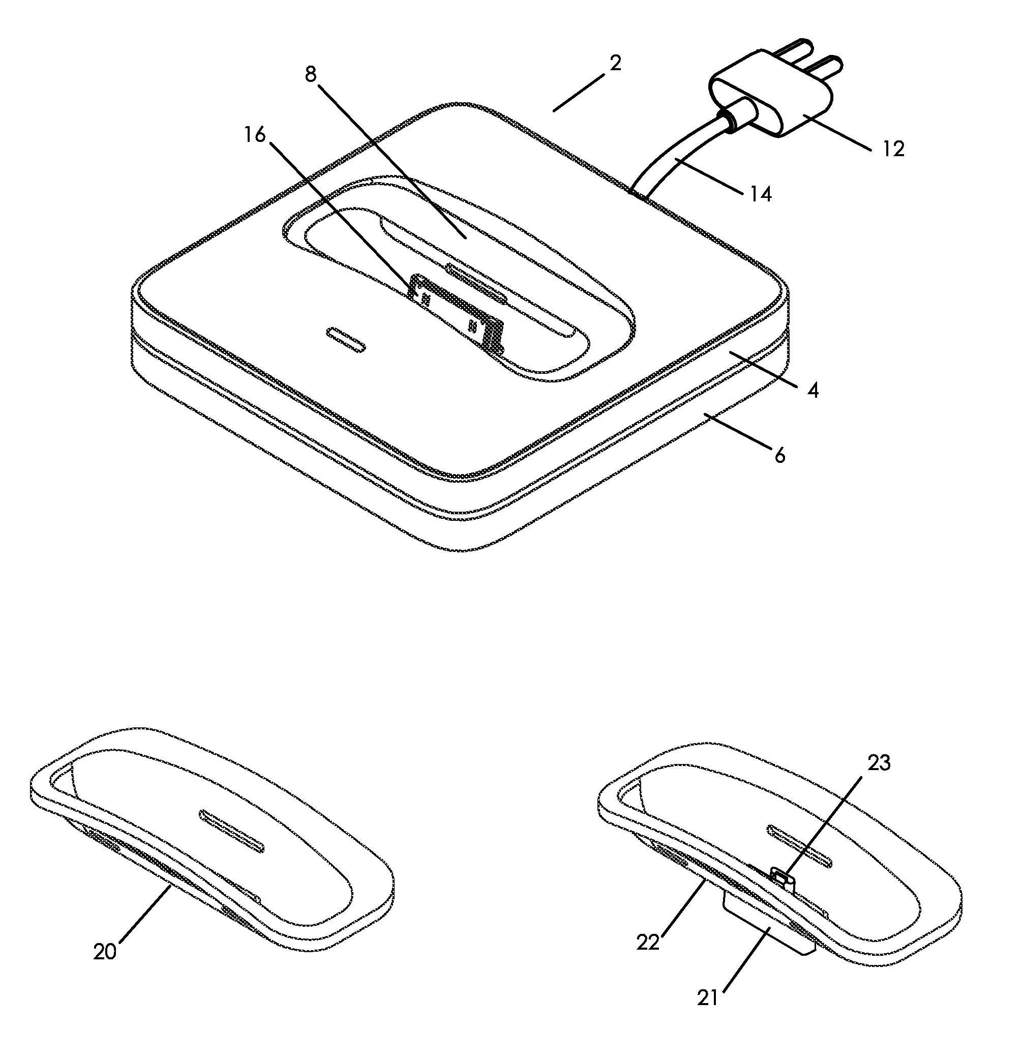
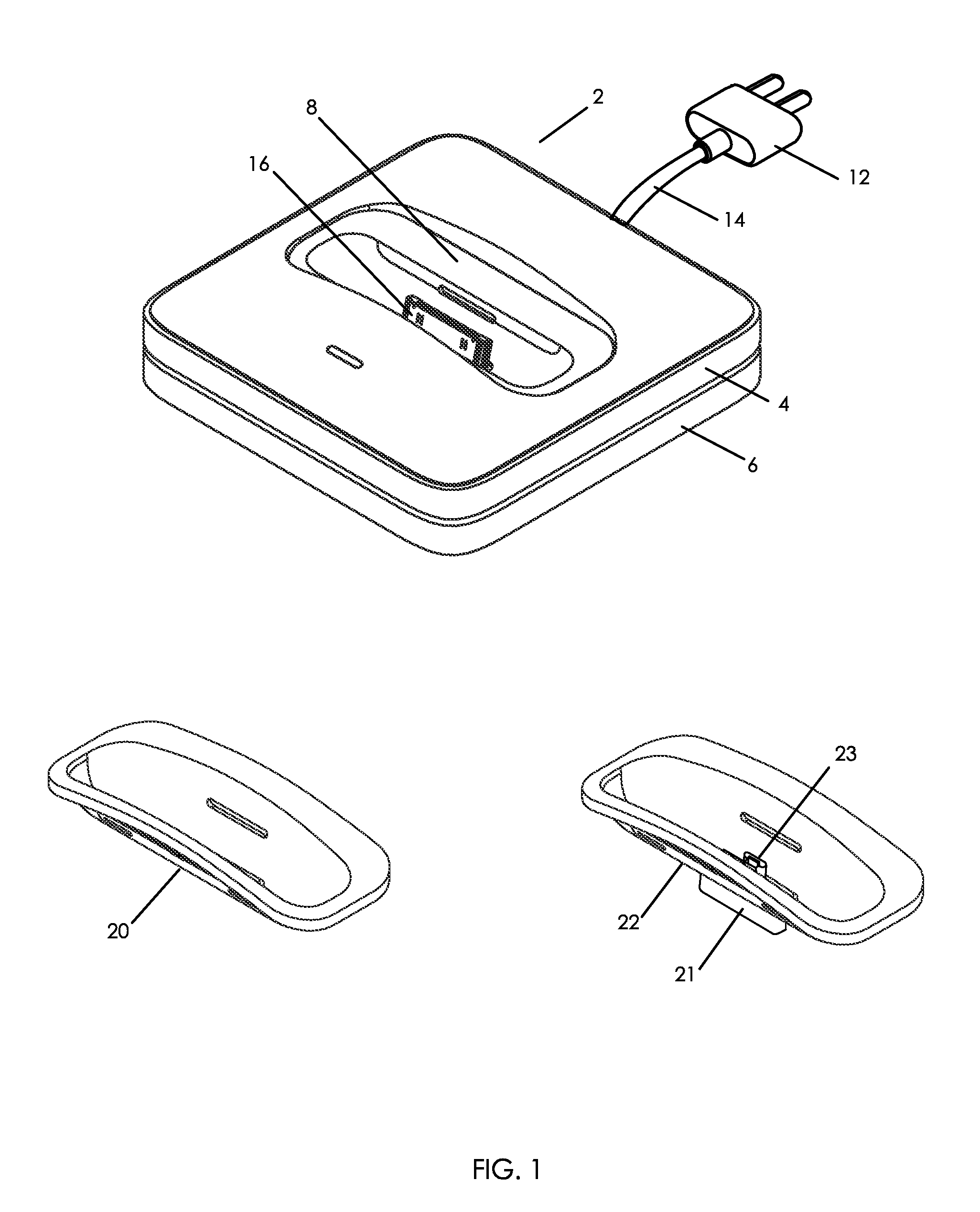
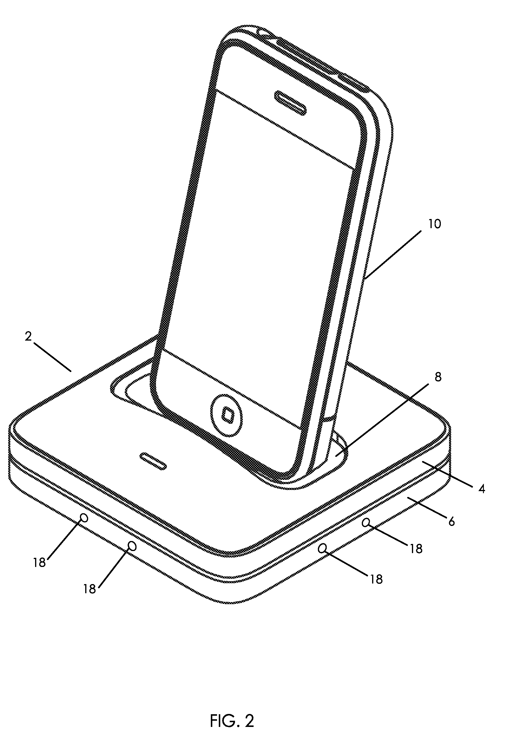
[0014]An illustration of a charging module 2 for a modular charger constructed in accordance with an embodiment of the present invention having electrified rails 4 and 6 is shown is FIG. 1. The charging module 2 is a square that has electrified rails 4 and 6 around its periphery. The rails 4 and 6 are adapted to receive and supply a DC bus voltage. The rails 4 and 6 are used to electrically connect adjacent modules. A DC bus voltage of 24 volts is preferably used so that a user can not seriously shock or harm them self by contacting the rails 4 and 6. A docking station 8 is provided on the module 2 that is adapted to receive an electronic device 10 as shown in FIG. 2. The docking station 8 has a connector 16 that is adapted to physically and electrically connect the portable electronic device 10 to the to the main body portion 2.

[0015]The main body portion of the charging module 2 receives power from an external power supply connector 12 such as household plug 12 and cable 14. An AC...


PUM


Abstract

A modular power supply that can be adapted to receive and charge practically any type or number of portable electronic devices includes a power converter that receives an AC wall voltage and converts the wall voltage to DC bus voltage. Each charging module has a pair of conductive rails and magnets positioned around the exterior of the module. The power converter has a connector that is physically and electrically coupled to a charging module through a pair of magnets and conductive rails such that the DC bus voltage is applied to the conductive rails of the module. Each charging module has a dock that physically couples to a portable electronic device and supplies a charging voltage produced from the DC bus voltage to the device. Additional charging modules can be physically and electrically coupled together by simply placing the modules adjacent one another through the interaction of the module's conductive rails and magnets. Adapters can be inserted into the docks of the charging modules to reconfigure the docks stations to mate with different types of devices. An FM transmitter can be included in one of the modules to transmit audio from the charging device to a remote FM receiver.

Description

CROSS-REFERENCES TO RELATED APPLICATIONS[0001]None.STATEMENT REGARDING FEDERALLY SPONSORED RESEARCH OR DEVELOPMENT[0002]Not ApplicableREFERENCE TO SEQUENCE LISTING OR COMPUTER PROGRAM LISTING APPENDIX[0003]Not ApplicableBACKGROUND OF THE INVENTION[0004]Portable electronic devices are increasingly common in modern society. Each of these portable devices has a rechargeable power supply that requires a corresponding power supply charger that conditions power received from a wall or car outlet to the voltage and current parameters required for the particular type of electronic device. As the number of devices increases, users have to maintain an increasing number of chargers to satisfy the requirements of their multiplying devices. Each home charger typically consists of a 100-240 volt plug attached to a transformer and an AC to DC voltage converter that produces the appropriate DC voltage for charging the particular type of electronic device and a device specific connector configured t...

Claims


Application Information

Patent Timeline
Patent Type & Authority Applications(United States)
IPC IPC(8): H02J7/02H02J7/00
CPCH02J7/022H02J7/0027H02J7/02H02J2207/20H02J7/0044H02J2310/22
Inventor GRIFFIN, JR., PAUL P.ROWAN, MARK DAVIDOWENS, DAVID ARNOLD
Owner VINCI BRANDS LLC
Why Eureka
Try Eureka