Solid-state microscope

a solid-state microscope and microscope technology, applied in the field of solid-state microscope devices, can solve the problems of irreversible degradation of biological samples, e.g., living cells, and drawbacks of conventional optical microscopes for specific microscopic applications, and achieve the effect of reducing the illumination power of conventional optical microscopes

Active Publication Date: 2010-02-11
STC UNM
View PDF11 Cites 80 Cited by
  • Summary
  • Abstract
  • Description
  • Claims
  • Application Information

AI Technical Summary

Benefits of technology

[0009]According to various embodiments, the present teachings further include a method for making a solid-state microscope. In this method, a GaN-based LED epitaxial layered structure can be provided including a multi-quantum well active region formed between an n-doped layer and a p-doped layer. The GaN-based LED epitaxial layered structure can be etched to the n-doped layer and whereby forming a plurality of LED mesa structures interspersed with one or more recessed spaces. On the surface of each recessed space and each mesa structure, a passivation layer can be deposited. An n-side metal contact can then be formed in the recessed space to connect with the n-doped layer through the passivation layer, followed by completely filling the recessed space with a dielectric material. P-side metal contacts can be formed on the p-doped layer of each LED mesa structure and further electrically connected with ROIC circuit cells.

Problems solved by technology

Such conventional optical microscopes, however, may have drawbacks and disadvantages for specific microscopic applications.
For example, when conventional optical microscopes are used to observe biological samples, the strong illumination power of the conventional optical microscopes may irreversibly degrade biological samples, e.g., living cells.
This is known as photo-toxicity in the prior art.

Method used


Image

  • Solid-state microscope
  • Solid-state microscope
  • Solid-state microscope

Examples


Embodiment Construction

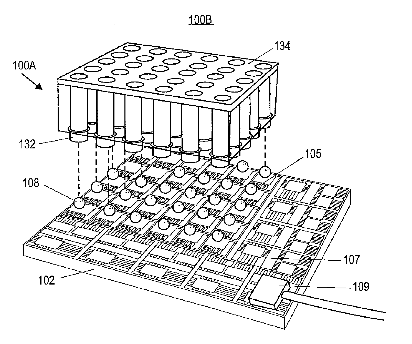
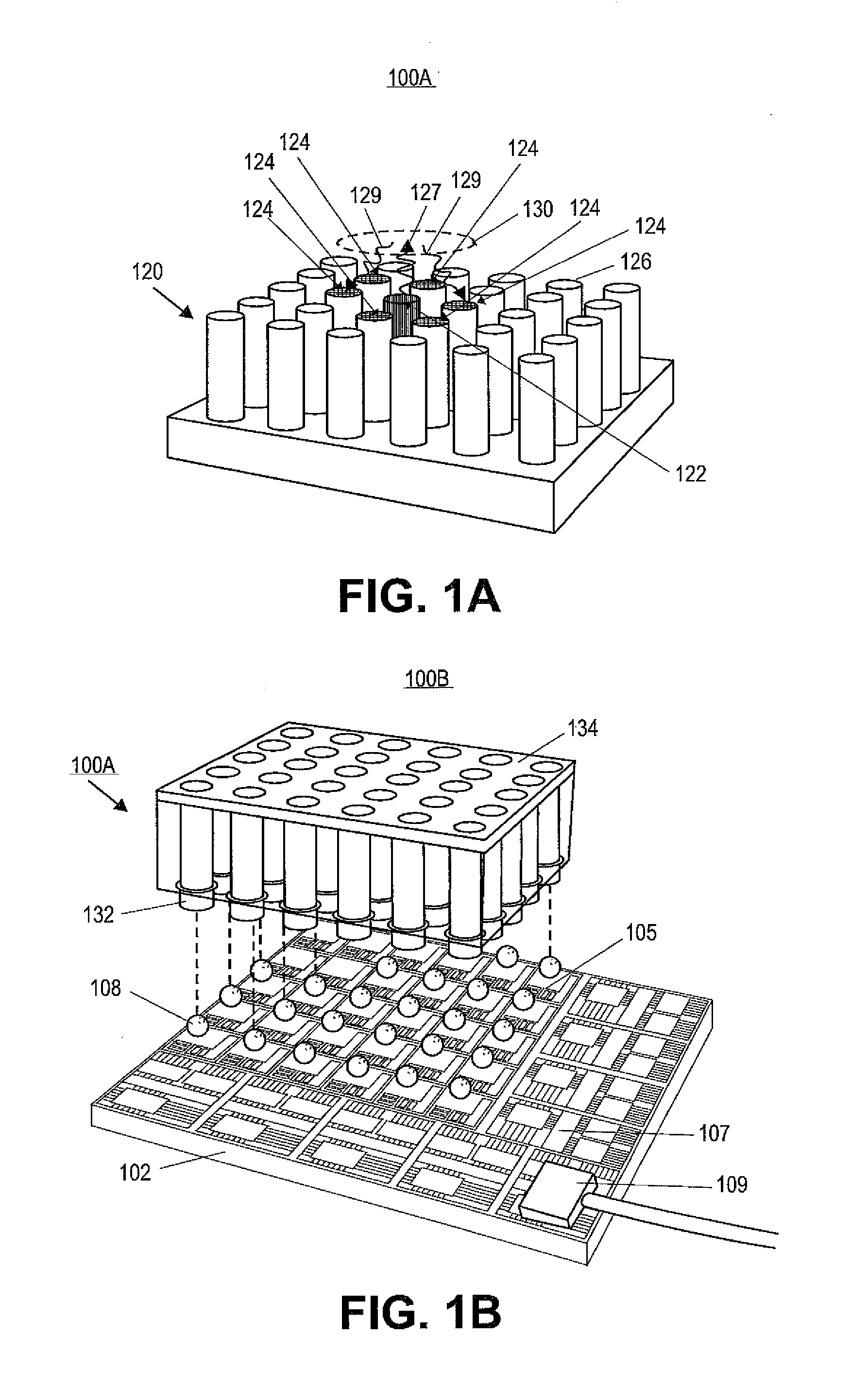
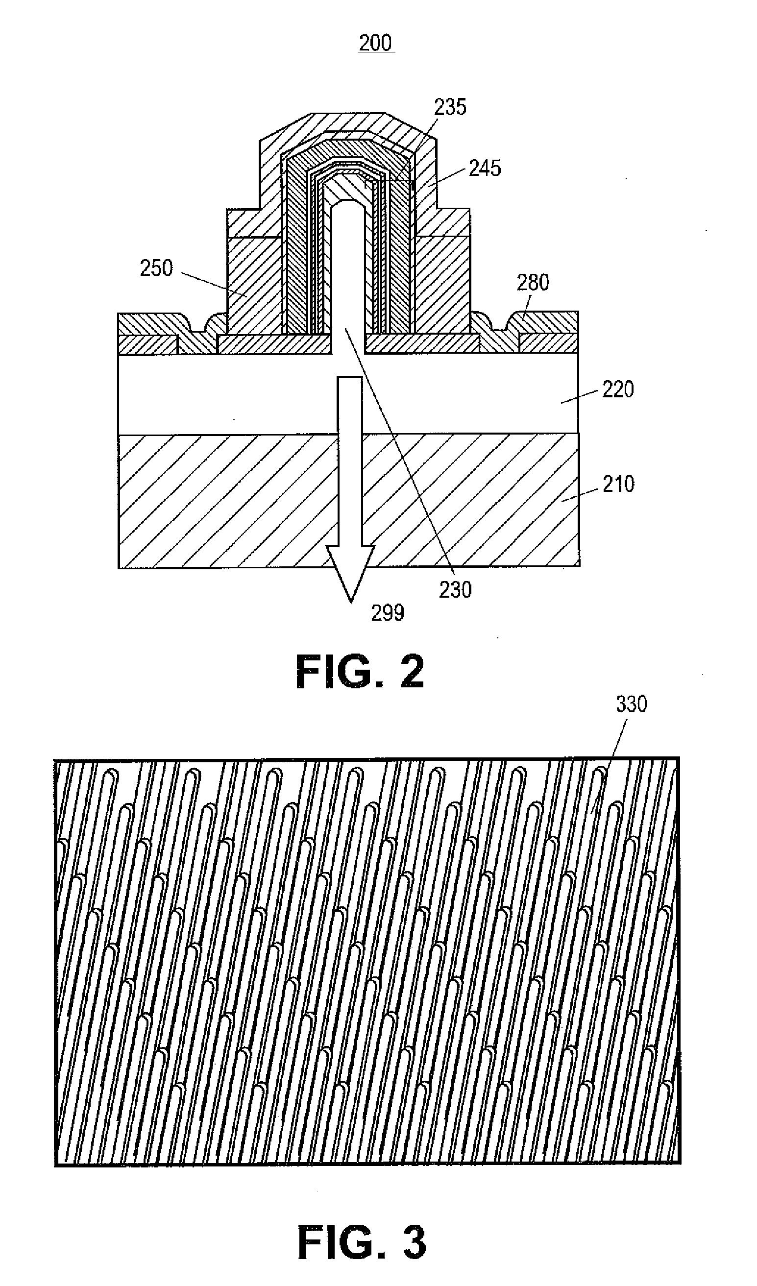
[0019]Reference will now be made in detail to exemplary embodiments of the invention, examples of which are illustrated in the accompanying drawings. Wherever possible, the same reference numbers will be used throughout the drawings to refer to the same or like parts. In the following description, reference is made to the accompanying drawings that form a part thereof, and in which is shown by way of illustration, specific exemplary embodiments in which the invention may be practiced. These embodiments are described in sufficient detail to enable those skilled in the art to practice the invention and it is to be understood that other embodiments may be utilized and that changes may be made without departing from the scope of the invention. The following description is, therefore, merely exemplary.

[0020]While the invention has been illustrated with respect to one or more implementations, alterations and / or modifications can be made to the illustrated examples without departing from t...


PUM


Abstract

Exemplary embodiments provide solid-state microscope (SSM) devices and methods for processing and using the SSM devices. The solid-state microscope devices can include a light emitter array having a plurality of light emitters with each light emitter individually addressable. During operation, each light emitter can be biased in one of three operating states including an emit state, a detect state, and an off state. The light emitter can include an LED (light emitting diode) including, but not limited to, a nanowire based LED or a planar LED to provide various desired image resolutions for the SSM devices. In an exemplary embodiment, for near-field microscopy, the resolution of the SSM microscope can be essentially defined by the pitch p, i.e., center-to-center spacing between two adjacent light emitters, of the light emitter array.

Description

RELATED APPLICATIONS[0001]This application claims priority from U.S. Provisional Patent Applications Ser. No. 60 / 913,927, filed Apr. 25, 2007, and Ser. No. 60 / 973,465, filed Sep. 19, 2007, which are hereby incorporated by reference in their entirety.GOVERNMENT RIGHTS[0002]This invention was made with government support under Contract No. HR0011-05-1-0006 awarded by Defense Advanced Research Projects Agency (DARPA). The government may have certain rights in the invention.FIELD OF THE INVENTION[0003]This invention relates generally to solid-state microscope devices and, more particularly, relates to lens-less semiconductor-based solid-state microscope devices and methods for their fabrication.BACKGROUND OF THE INVENTION[0004]A conventional optical microscope uses optical lenses to gather light from an illuminated object and provide a magnified image of that object to the viewer. An additional light source, that itself may require conditioning optics, is often used to illuminate the sa...

Claims


Application Information

Patent Timeline
Patent Type & Authority Applications(United States)
IPC IPC(8): H04N7/18H01L33/00H01L21/28
CPCB82Y15/00B82Y20/00H01L33/18G02B21/002H01L27/156G02B21/00G02B21/0004G02B21/06G02B21/36G02B21/361H01L33/0025H01L33/0075H01L33/06H01L33/24H01L33/32H01L33/36H01L2933/0016
Inventor HERSEE, STEPHEN D.
Owner STC UNM
Why Eureka
Try Eureka