Wireless system

a wireless system and wireless technology, applied in the field of wireless communications networks, can solve problems such as difficult frequency allocation, interference in other areas, and gaps in the coverage area of cellular systems, and achieve the effects of facilitating handover between base stations and relay stations, reducing interference, and reducing interferen

Active Publication Date: 2010-02-11
APPLE INC
View PDF6 Cites 105 Cited by
  • Summary
  • Abstract
  • Description
  • Claims
  • Application Information

AI Technical Summary

Benefits of technology

[0023]The benefit of this method is that interference is prevented between control data transmitted by a base station and control data transmitted by a relay station as received at user equipment. For example, a base station may be equipped to give wireless coverage to a sector and a relay station may be operating within the area of coverage of the base station. A user equipment may be pre-programmed to receive control data within a radio resource element or elements that may for example be a control timeslot within a frame structure allocating radio resource within a network.
[0030]Preferably, the network is configured such that regions of coverage in which signals from base stations suffer interference do not coincide with regions of coverage in which signals from relay stations suffer interference. The benefit is that the base stations may be operated with a n=1 frequency reuse scheme that gives high capacity close to base stations at the cost of interference at the boundaries between the areas of coverage of base station. Similarly, the relay stations can operate a n=1 frequency reuse scheme at a separate frequency sub-band from those used by the base stations. Provided the boundary regions associated with the base stations and the relay stations do not coincide, the network can provide efficient use of the spectrum as a user equipment can receive signals from whichever base station or relay station is providing the best carrier to interference ratio and hence the best data capacity at a given location in the network.

Problems solved by technology

There may be gaps in the area of coverage of a cellular system due to shadowing by the terrain or by interference between signals transmitted by base stations.
However, a repeater station that simply retransmits all signals received within a band may cause interference that reduces coverage in other areas.
However, it may be problematic to allocate frequency sub-bands to relay stations deployed within a conventional cellular wireless network employing n=3 frequency re-use in a way that does not result in interference.
Therefore, techniques that mitigate the effects of interference between base stations and between base station sectors by the intelligent combination of potentially interfering signals that carry the same information are not generally applicable for use with control timeslots.
For example, soft handover and best server selection methods are generally not applicable for use with the control timeslot as they would impose the limitation that the information content of potentially interfering signals would be the same.
Therefore, if the same sub-band is allocated to the relay station 10 as to the base station 2, there is the potential for interference to occur between control data transmitted from the base station 2 and control data transmitted from the relay station 10.
In practice, relay stations are of most value when placed at the extremes of coverage of a base station sector, since it is here that augmentation of coverage are most likely to be required, but it is also in this situation that interference is most likely to be caused.
In addition, interference may be experienced between transmissions from adjacent relay stations which may be operating in the same sub-band.
The use of a relay station within the area of coverage of a conventional cellular wireless network using n=3 frequency re-use thus can potentially cause interference with signals transmitted from base stations and with signals transmitted from neighbouring relay stations.

Method used


Image

  • Wireless system
  • Wireless system
  • Wireless system

Examples


Embodiment Construction

[0048]In general, the present invention is directed to methods and apparatus that are aimed to increase the capacity or coverage of a cellular wireless system by the use of relay stations. For clarity, the methods and apparatus are described in the context of a high speed packet data system such as IEEE802.16 (WiMax) or LTE, but it will be appreciated that this is by way of example and that the methods and apparatus described are not limited to these examples.

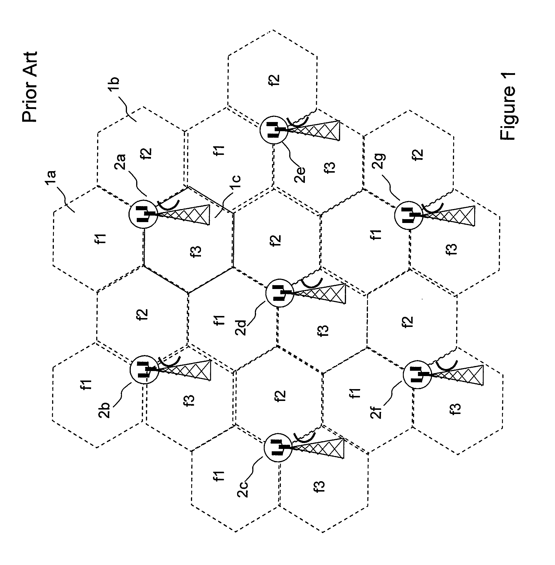
[0049]As a result of the problems of interference mentioned above, the potential capacity increase offered by the use of relay stations within a cellular wireless network using a conventional n=3 frequency reuse scheme is limited.

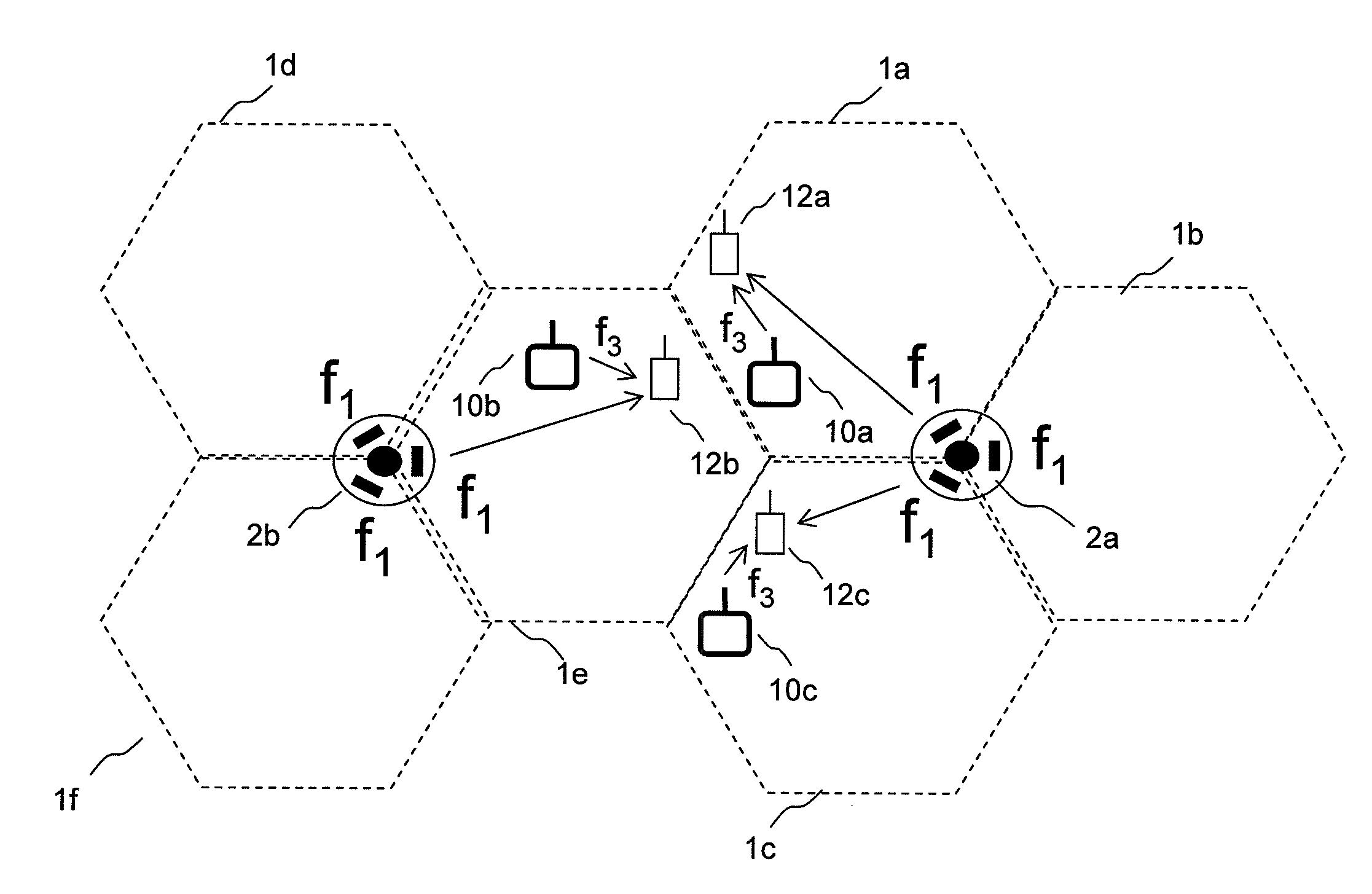
[0050]FIG. 6 illustrates a similar network to that illustrated in FIG. 5, with an improved frequency re-use scheme according to an embodiment of the invention. In contrast to conventional cellular wireless systems in which the base stations operate within a frequency re-use scheme of n=3, in the system...


PUM


Abstract

The capacity of a cellular wireless system is increased by operation of base stations or base station sectors arranged to re-use radio resource elements that are used by neighbouring base stations or base station sectors, in conjunction with operation of relay stations, which are similarly arranged to re-use radio resource elements used by neighbouring relay stations, and where the radio resource elements re-used by the relay stations are different to those used by the base stations. The relay stations provide coverage, particularly in the areas at the boundaries between the areas of coverage of base stations that suffer from interference between signals transmitted from the respective base stations. In addition, the relay stations generally increase the average available carrier to interference ratio compared with a system in which base stations alone are deployed. The scheme for the allocation of radio resource elements ensures in particular that interference is avoided between signals transmitted from a base station and signals transmitted from a relay station in radio resource elements allocated to control data.

Description

FIELD OF THE INVENTION [0001]The present invention relates generally to wireless communications networks, and more specifically to a method and a system relating to multi-hop or relay enhanced cellular wireless systems.BACKGROUND OF THE INVENTION [0002]Mobile telephony systems in which user equipment such as mobile handsets communicate via wireless links to a network of base stations connected to a telecommunications network have undergone rapid development through a number of generations. The initial deployment of systems using analogue modulation has been superseded by second generation digital systems, which are themselves currently being superseded by third generation digital systems such as UMTS and CDMA. Third generation standards provide for a greater throughput of data than is provided by second generation systems; this trend is continued with the proposal by the Third Generation Partnership Project of the so-called Long Term Evolution system, often simply called LTE, which ...

Claims


Application Information

Patent Timeline
Patent Type & Authority Applications(United States)
IPC IPC(8): H04Q7/20H04M1/00
CPCH04B7/15542H04B7/2606H04W84/047H04W72/044H04W72/04H04L5/0041H04L5/0007H04L5/0044H04W72/0453H04W72/52H04W72/27H04L27/2627H04W16/12H04W72/0446
Inventor NADEN, JAMES MARKZHU, PEIYING
Owner APPLE INC
Why Eureka
Try Eureka