Hemostasis valve

a technology of hemostasis valve and valve body, which is applied in the field of hemostasis valve, can solve the problems of hemostasis loss, large amount of blood and other fluids that can be lost from the patient, and the removal and insertion of another medical instrument, so as to prevent blood loss

Inactive Publication Date: 2010-02-11
RAZACK NASSER
View PDF14 Cites 69 Cited by
  • Summary
  • Abstract
  • Description
  • Claims
  • Application Information

AI Technical Summary

Benefits of technology

[0007]To achieve these and other advantages, in general, in one aspect, a hemostasis valve for preventing blood loss while permitting the introduction of intravascular instruments is provided. The hemostasis valve includes a valve body having a lumen extending therethrough, a first valve positioned across the lumen that is operable to selectively permit fluid flow through the lumen in an open position or preclude fluid flow through the lumen in a closed position, a second valve positioned across the lumen that is operable to selectively pe

Problems solved by technology

One of the problems found in conventional hemostasis valves is the reposition, the removal and insertion of another medical instrument, or the insertion of multiple medical instruments through a single

Method used


Image

  • Hemostasis valve
  • Hemostasis valve
  • Hemostasis valve

Examples


Embodiment Construction

[0023]Referring now to the drawings, the same reference numerals are used to identify like parts of the illustrated embodiments. The present invention relates to an improved hemostasis valve apparatus that minimizes the loss of body fluids during insertion, repositioning or removal of intravascular medical instruments.

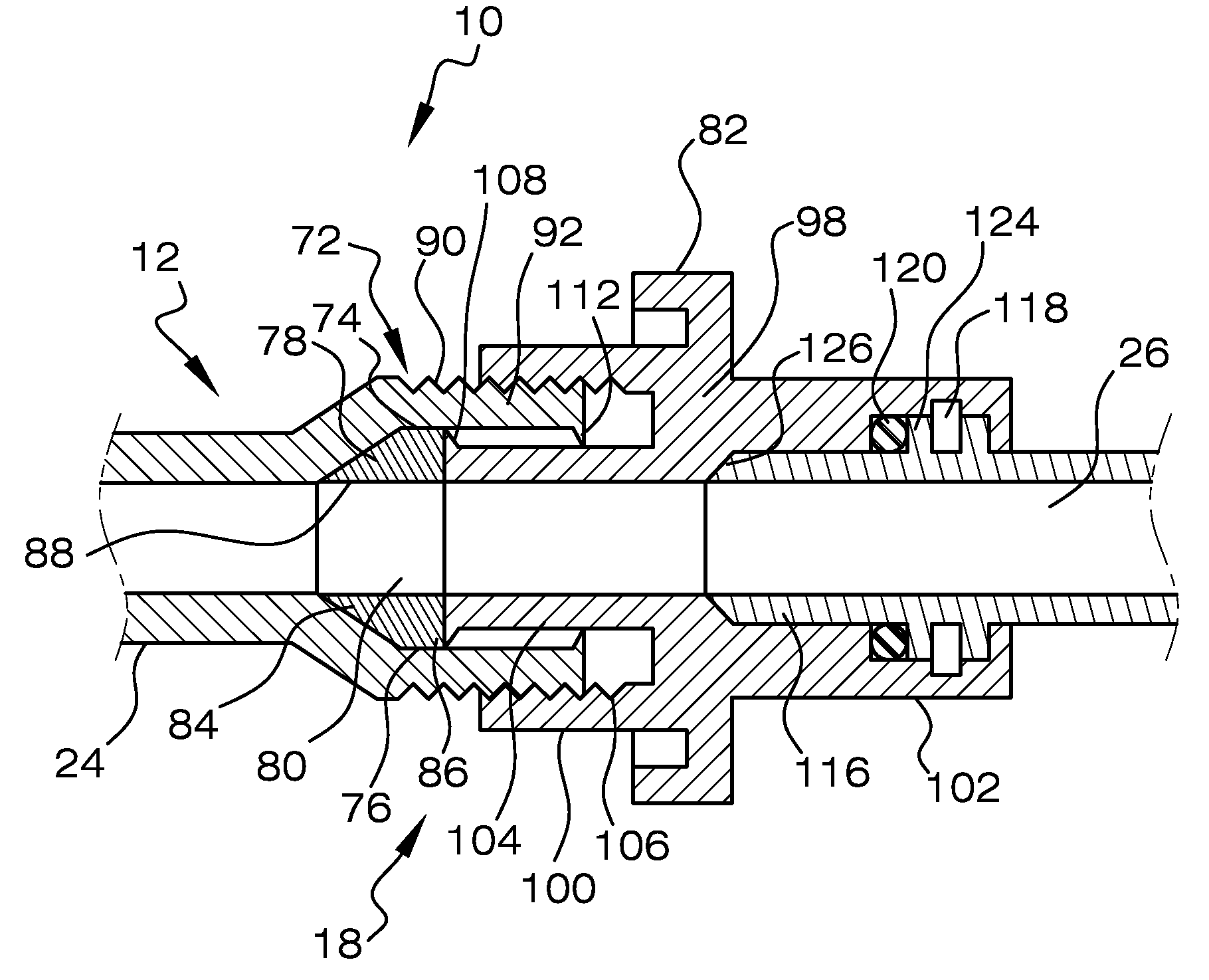
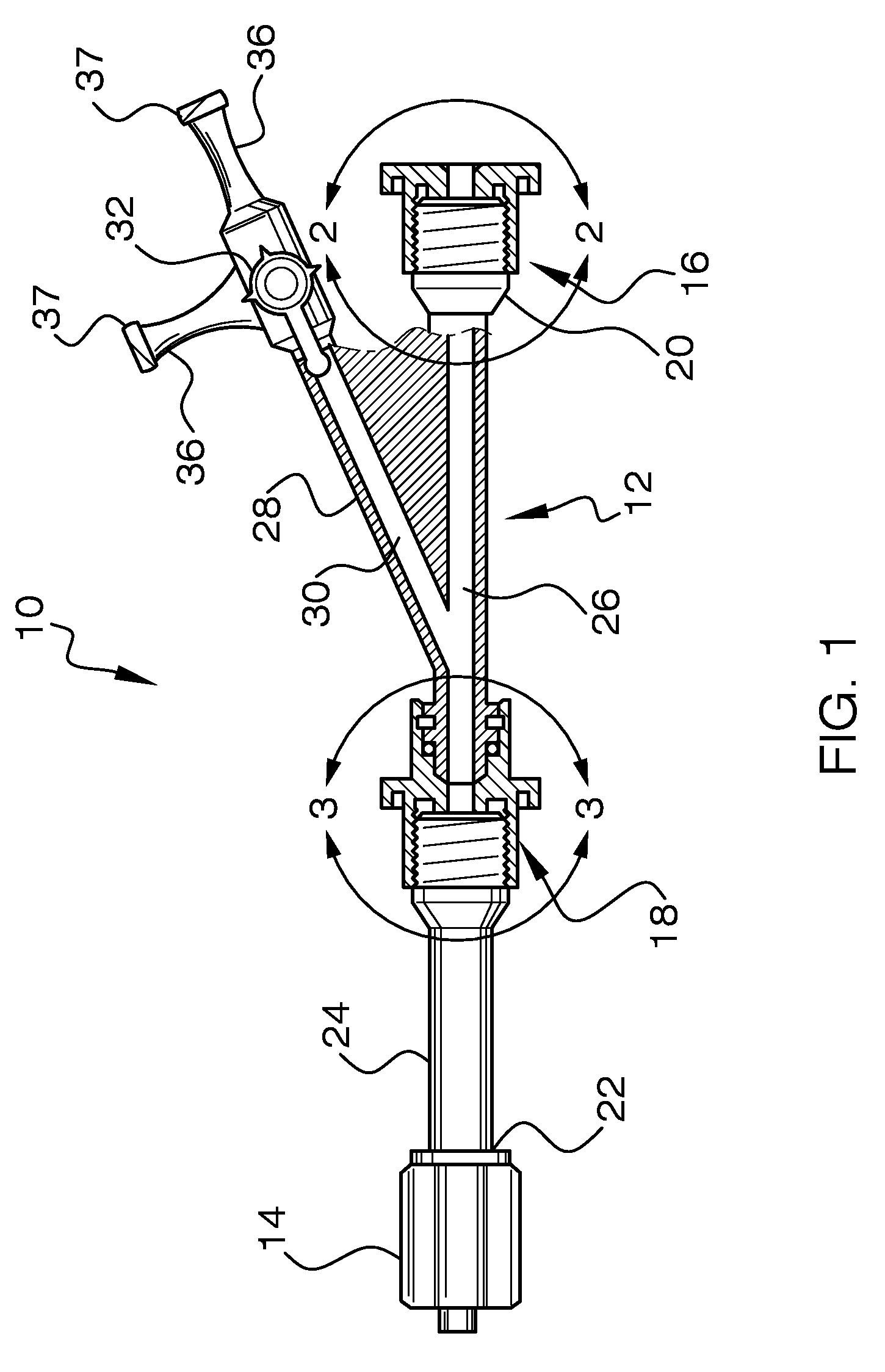
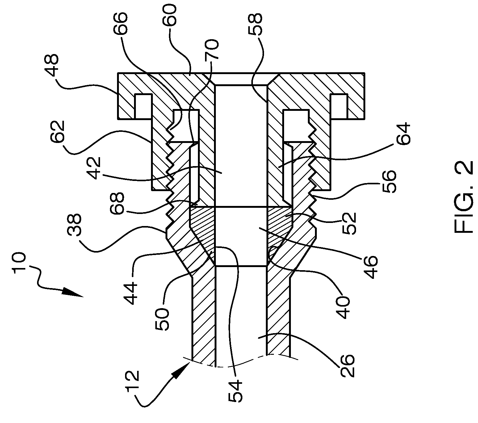
[0024]Referring now to FIG. 1, which illustrates a hemostasis valve 10 according to the present invention. The hemostasis valve 10 includes a valve body 12, a rotatable connector 14, a first valve 16, and a second valve 18. The first and second valves 16 and 18 are longitudinally spaced along the valve body 12. The valve body 12 has a proximal end 20, an opposing distal end 22, an intermediate barrel portion 24, and a through-lumen 26. Rotatable connector 14 is positioned at the distal end 22 of the valve body 12. Rotatable connector 14 is an example of a means for rotatably coupling said valve body 12 in fluid communication with a catheter or other medical device. The...


PUM


Abstract

A hemostasis valve to maintain hemostasis during the insertion, removal or reposition of a medical instrument in the vascular system of a patient. The hemostasis valve includes a valve body having lumen extending therethrough, a first valve positioned across the lumen, and having a passage with a diameter that is continuously variable, a second valve positioned across the lumen, and having a passage with a diameter that is continuously variable. The first and second valves being spaced apart longitudinally along the lumen. A connector rotatably attached to the valve body for connecting the hemostasis valve to another instrument. The first and second valves are selectively operable to create an opening through the passage respectively of a diameter to permit admittance of at least one intravascular instrument through at least one of the first and second valves while maintaining hemostasis. The second valve is rotatably attached to the valve body without effecting the diameter of the passage therethrough.

Description

FILED OF THE INVENTION[0001]The present invention relates generally to an apparatus that can be used to limit or prevent the loss of bodily fluids from a patient when an access device is introduced into the body of patient, and more particularly, relating to a hemostasis valve for use in medical procedures.BACKGROUND OF THE INVENTION[0002]Hemostasis valves are well known and used in medical procedures requiring the insertion of a catheter or other device into the vascular system of a patient.[0003]Hemostasis valves are used for leak-proof introduction of catheters or other devices into the vascular system or elsewhere in the body of a patient. Typically, a guide catheter is connected to the distal end of the hemostasis valve, and an operating instrument is inserted into the proximal end and through the guide catheter to the desired location in the patient. Once the operating instrument is in place, the valve is closed around the instrument to prevent blood from escaping from the bod...

Claims


Application Information

Patent Timeline
IPC IPC(8): A61M39/22
CPCA61M39/22A61M39/0613
Inventor RAZACK, NASSER
Owner RAZACK NASSER
Why Eureka
Try Eureka