
Collapsible bone screw apparatus

a bone screw and apparatus technology, applied in the field of bone screw, can solve the problems of the distal end of the screw protruding from the bone, pain to the patient, and interference with ambulation, and achieve the effect of shortening the overall length

Active Publication Date: 2010-02-11
ARCH DAY DESIGN
View PDF42 Cites 39 Cited by
  • Summary
  • Abstract
  • Description
  • Claims
  • Application Information

AI Technical Summary

Benefits of technology

[0021]In a further aspect, a method is provided for surgically fastening bone fragments. The method comprises screwing a threaded inner screw member into a first bone portion, movably joining a threaded outer screw to the inner screw member, screwing the outer screw member into a second bone portion after screwing the threaded inner screw member, and preventing the outer screw member from protruding out of the second bone portion over time by decreasing a total length between the inner screw member and the outer screw member.
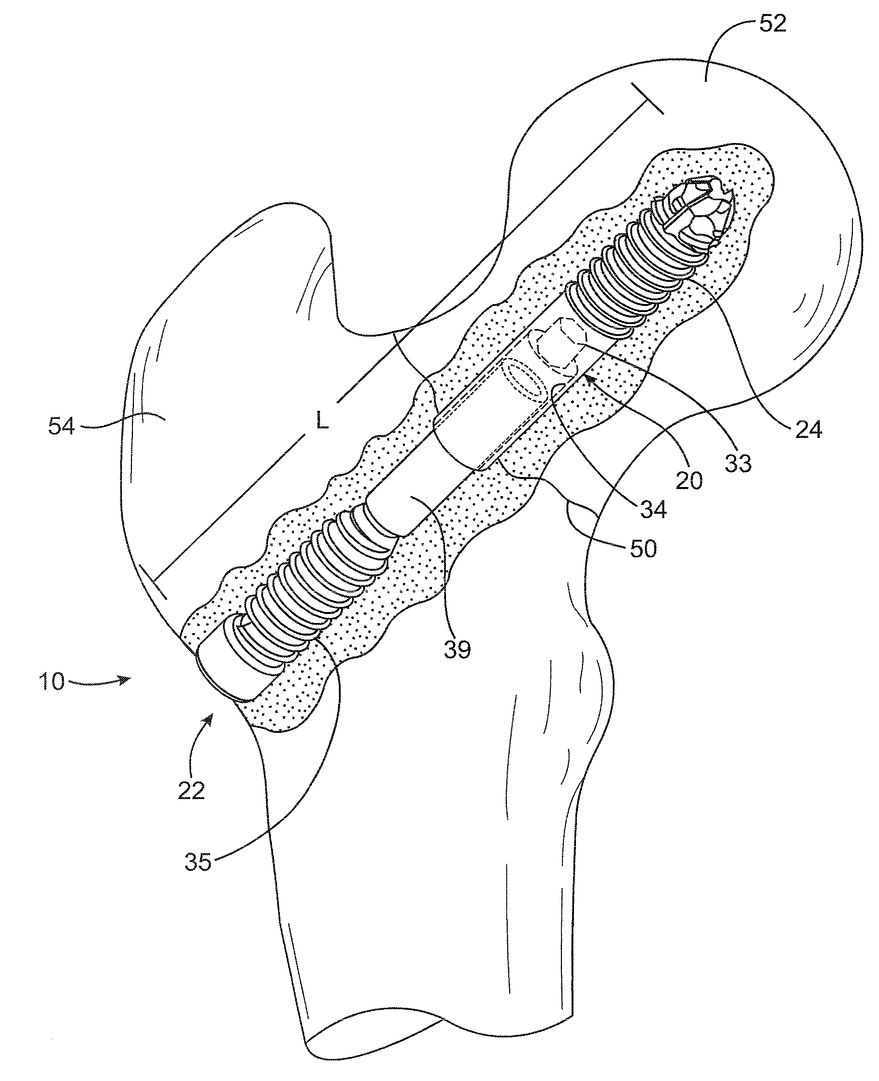
[0026]A collapsible bone screw for healing bone fragments across a bone fracture includes an externally threaded inner screw member and an externally threaded outer screw member. The inner screw member is initially screwed into an inner bone portion. An unthreaded portion of the outer screw member is movably joined to the inner screw member. The outer screw member is screwed until it gains purchase in an outer bone portion. As impaction occurs over time, the collapsible bone screw apparatus may shorten in length as the two screw members slide, telescope or otherwise axially move toward each other to shorten the overall length, thereby preventing any portion of the screw apparatus from protruding out of the bone. A bone screw kit of multiple inner and outer screw members are provided as well as a method of surgically fastening bone fragments.

Problems solved by technology

However, over time, impaction can take place near the fractured bone surfaces, which may cause the distal end of the screw to protrude from the bone in which it was initially embedded.
When this occurs, the protruding portion can cause pain to the patient, interfere with ambulation, and may require a second surgery for removal of the screw.

Method used


Image

  • Collapsible bone screw apparatus
  • Collapsible bone screw apparatus
  • Collapsible bone screw apparatus

Examples


Embodiment Construction

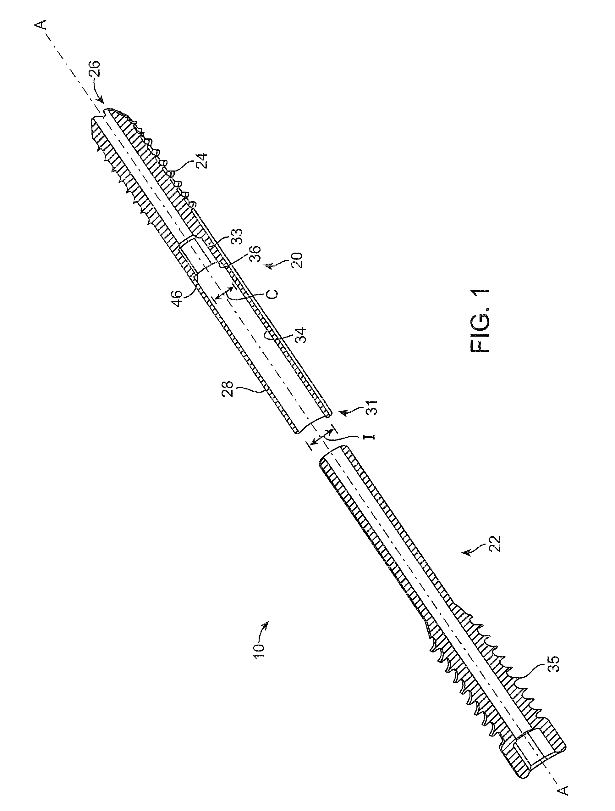
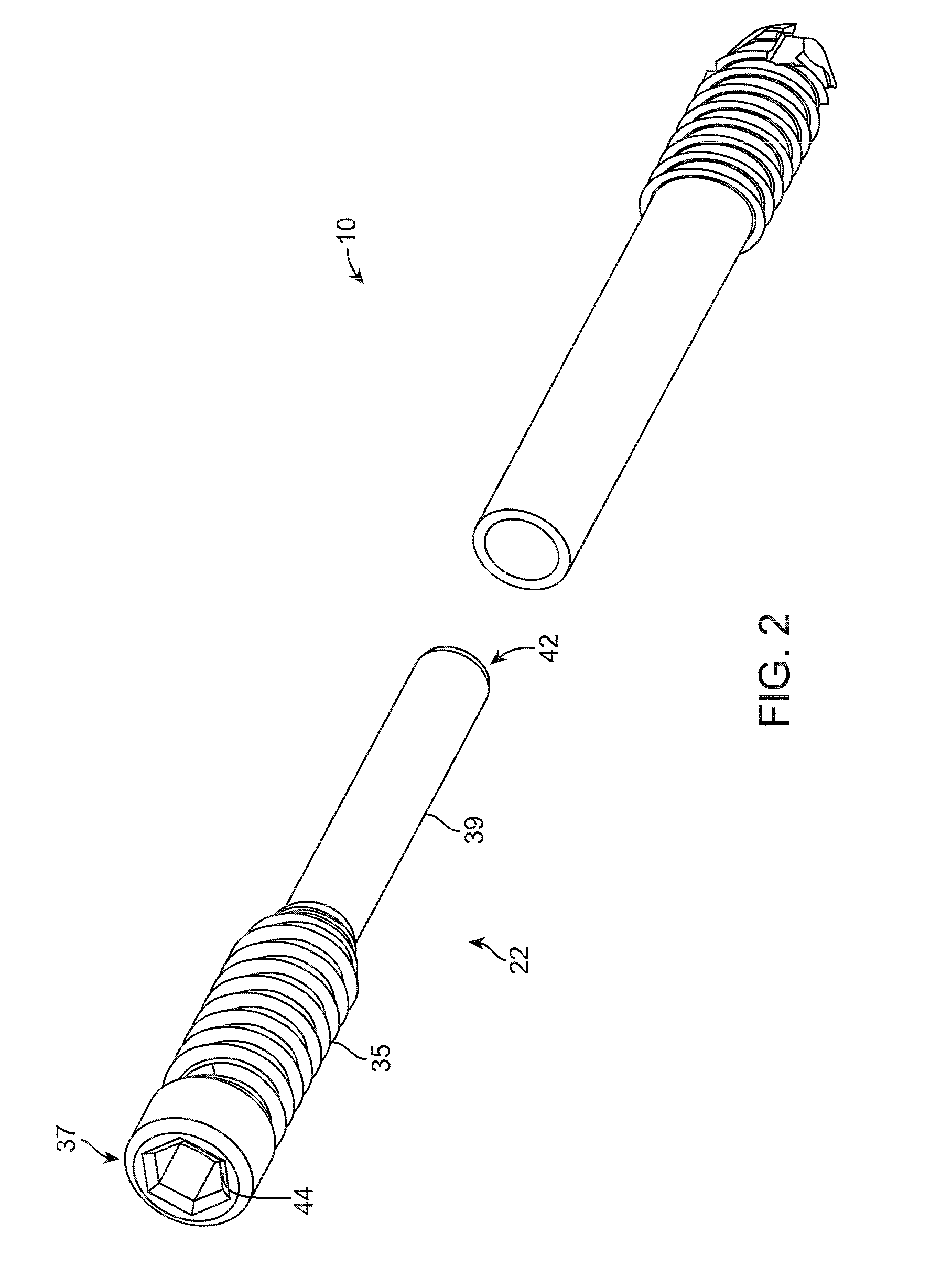
[0036]A first preferred embodiment of a collapsible bone screw apparatus is illustrated in FIG. 1 and designated generally by the reference numeral 10. The multi-piece screw apparatus 10 is configured for fastening together bone fragments, particularly where impaction occurs to effect healing, such as in the femoral neck. As used throughout the specification, the terms “inner,”“inward” and “medial” refer to the center of the patient for which the apparatus is used, whereas “outer,”“outward” or “lateral” refer to a location and direction away from the center of the patient.

[0037]In FIG. 1, the bone screw apparatus 10 comprises an inner, or medial, screw member 20 and an outer, or lateral, screw member 22, which are configured to be joined to each other and movably adjustable along an axis “A.” The inner screw member 20 preferably comprises a shaft including an externally threaded portion 24 adjacent to a far end 26. The external portion 24 may also comprise other means for attaching ...


PUM


Abstract

A collapsible bone screw for healing bone fragments across a bone fracture includes an externally threaded inner screw member and an externally threaded outer screw member. The inner screw member is initially screwed into an inner bone portion. An unthreaded portion of the outer screw member is movably joined to the inner screw member. The outer screw member is screwed until it gains purchase in an outer bone portion. As impaction occurs over time, the collapsible bone screw apparatus may shorten in length as the two screw members slide, telescope or otherwise axially move toward each other to shorten the overall length, thereby preventing any portion of the screw apparatus from protruding out of the bone. A bone screw kit of multiple inner and outer screw members are provided as well as a method of surgically fastening bone fragments.

Description

RELATED APPLICATIONS[0001]This application relates to, claims priority from, and incorporates herein by reference, as if fully set forth, the following:[0002]1) U.S. Provisional Patent Application Ser. No. 61 / 188,724 filed on Aug. 11, 2008 and entitled “COLLAPSING BONE SCREW”; and[0003]2) U.S. Provisional Patent Application Ser. No. 61 / 189,074 filed on Aug. 15, 2008 and entitled “COLLAPSING BONE SCREW”.BACKGROUND OF THE INVENTION[0004]1. Field of the Invention[0005]The invention relates generally to surgical devices and methods, and more particularly to bone screws for surgically fastening bone fractures.[0006]2. Description of Prior Art and Related Information[0007]Conventionally, a bone screw used to surgically fasten together fractured bone fragments consists of a one-piece device having two ends. The screw has a set of threads at its proximal end—i.e., the end that will be nearest the center of the body when the screw is in place.[0008]In use, a guide pin is inserted across the ...

Claims


Application Information

Patent Timeline
Patent Type & Authority Applications(United States)
IPC IPC(8): A61B17/86
CPCA61B17/72A61B17/742A61B17/702A61B17/8685A61B17/864
Inventor MORRIS, STEPHENWEISEL, TOMPISARNWONGS, ROGER
Owner ARCH DAY DESIGN
Learn More