Monitoring of heat exchangers in process control systems

a technology of process control system and heat exchanger, which is applied in the direction of instruments, heat measurement, lighting and heating apparatus, etc., can solve the problems of not being able to discern when cleaning is required, and affecting the operation of the system

Inactive Publication Date: 2010-02-11
SIEMENS AG
View PDF6 Cites 8 Cited by
  • Summary
  • Abstract
  • Description
  • Claims
  • Application Information

AI Technical Summary

Benefits of technology

[0032]False alarms are avoided by freezing calculation in the case of unsteady transition processes.

Problems solved by technology

This is very complex on the one hand and involves significant costs on the other.
A particular drawback is that the deposits are often not visible from the outside.
Therefore it is not possible to discern when cleaning is required.
Cleaning is frequently only carried out if problems caused by the poor efficiency of the heat exchanger occur.
This is also disadvantageous as in such a case the heat exchanger is then cleaned even if the deposits are still not very heavy.
Until now there has therefore been no satisfactory solution to the monitoring of heat exchangers within a process control system, in particular if the heat exchangers are operated at different working points in the operating phase because for example flow or temperature of the product are not constant.

Method used


Image

  • Monitoring of heat exchangers in process control systems
  • Monitoring of heat exchangers in process control systems
  • Monitoring of heat exchangers in process control systems

Examples


Embodiment Construction

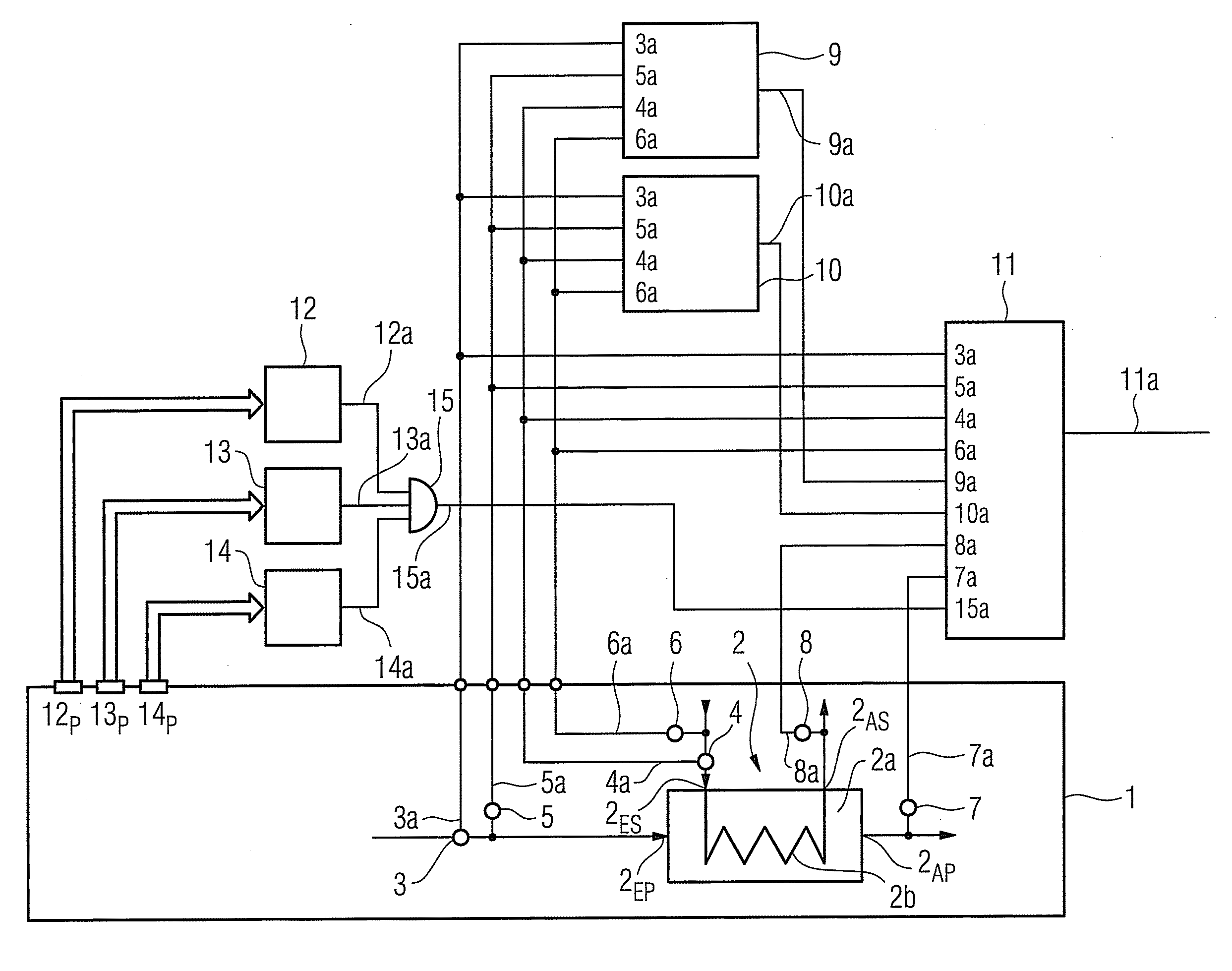
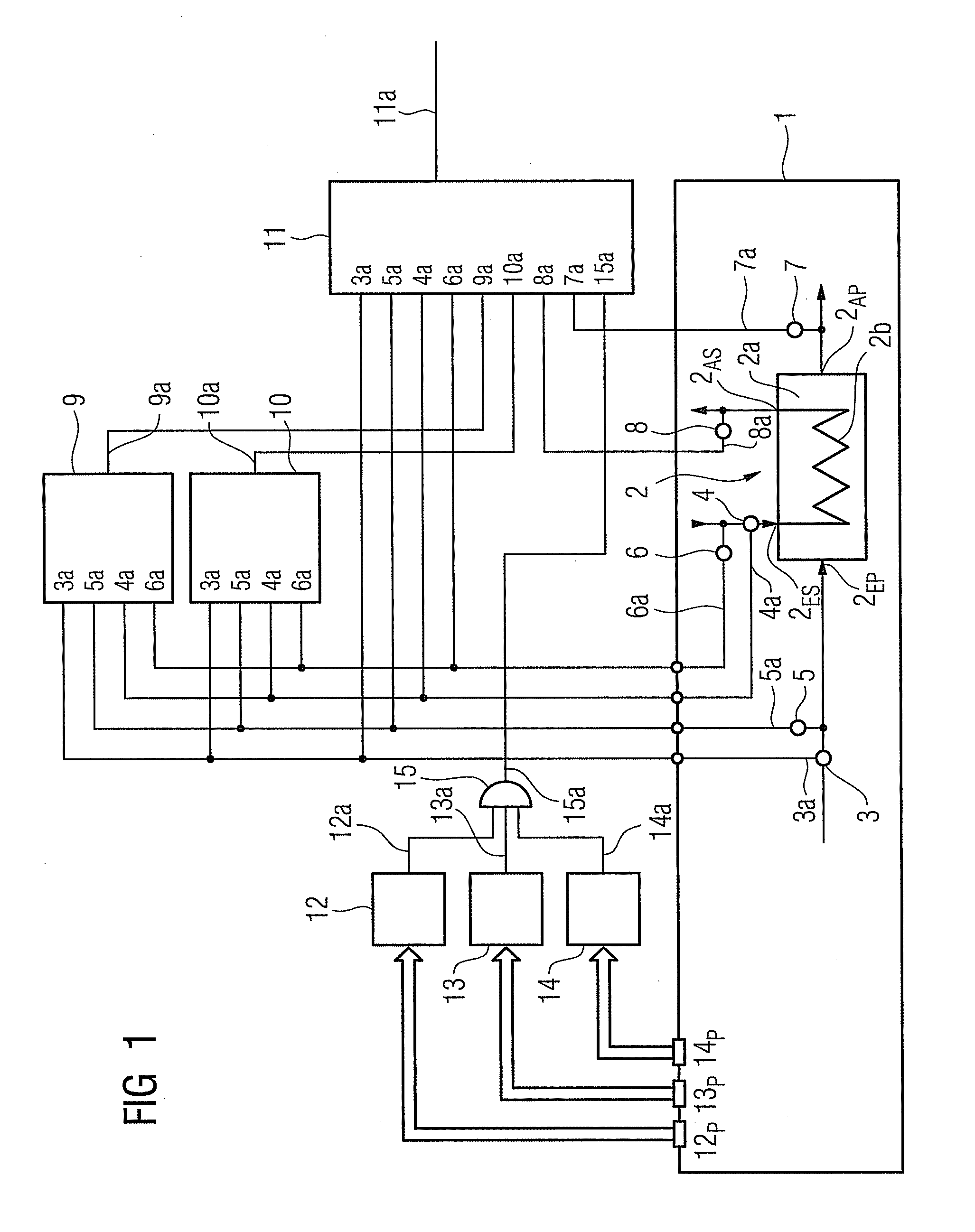
[0036]As may be inferred from FIG. 1, a process plant 1 has a heat exchanger 2. The heat exchanger 2 has a receptacle 2a in which a pipeline arrangement 2b is disposed. The receptacle 2a has a first entrance 2EP and a first exit 2AP. A product medium flows via the first entrance 2EP into the receptacle 2a and leaves it again at the first exit 2AP.

[0037]The pipeline arrangement 2b is led out of the receptacle 2a of the heat exchanger 2 via a second entrance 2ES and via a second exit 2AS. A service medium can be guided into the pipeline arrangement 2b via the second entrance 2ES and leaves it again at the second exit 2AS.

[0038]The volume of product medium supplied to the receptacle 2a can be detected by means of a first flowmeter 3. The volume of service medium supplied to the pipeline arrangement 2b can be detected by means of a second flowmeter 4. The temperature of the product medium supplied to the receptacle 2a can be detected at the first entrance 2EP of the receptacle 2a by mea...


PUM

PropertyMeasurementUnit
heat flowaaaaaaaaaa
temperatureaaaaaaaaaa
thicknessaaaaaaaaaa

Abstract

A method for monitoring the efficiency of a heat exchanger is provided. Heat flows from a first medium into a second medium and an actual heat flow is detected and compared with at least one reference heat flow corresponding to a respectively predetermined degree of soiling of the heat exchanger. Furthermore, a device for controlling a plant having at least one heat exchanger is described. The plant has a storage device storing at least one reference heat flow of the heat exchanger.

Description

CROSS REFERENCE TO RELATED APPLICATIONS[0001]This application claims priority of European Patent Application No. 08009815.5 EP filed May 29, 2008, which is incorporated by reference herein in its entirety.FIELD OF INVENTION[0002]The invention relates to a method for monitoring the efficiency of a heat exchanger in which heat flows from a first medium into a second medium. The invention also relates to a device for controlling a plant having at least one heat exchanger.SUMMARY OF INVENTION[0003]Heat exchangers are technical apparatuses in which for example liquids at a first temperature dissipate a portion of their heat to liquids at a second temperature that is below the first temperature for example. Thus for example a first medium (product medium) can be cooled or heated by means of a second medium (service medium). The service medium can for example be cooling water or heating steam. The service medium conventionally flows either through a pipeline arrangement, which is disposed ...

Claims


Application Information

Patent Timeline
Patent Type & Authority Applications(United States)
IPC IPC(8): G01K17/00G06F15/00F28F7/00
CPCF28G15/00F01K13/02F28G15/003F28F2200/00
Inventor FRIEDRICH, MICHAELGRIEB, HERBERTMULLER-HEINZERLING, THOMASPFEIFFER, BERND-MARKUSSCHULER, MICHAEL
Owner SIEMENS AG
Why Eureka
Try Eureka