Piezoelectric actuator and electronic apparatus

a piezoelectric actuator and actuator technology, applied in the field of piezoelectric actuators and electronic devices, can solve the problems of not taking into account the use of piezoelectric actuators as speakers for reproducing music or voice, and the drawback of obtaining sufficient sound pressure levels only in the vicinity of the resonant frequency, and achieve the effect of low rigidity

Inactive Publication Date: 2010-02-18
NEC CORP
View PDF10 Cites 36 Cited by
  • Summary
  • Abstract
  • Description
  • Claims
  • Application Information

AI Technical Summary

Benefits of technology

[0009]When considering the frequency characteristics that are required as an acoustic element, not only increasing the amplitude in limited frequencies but also the manner in which the amplitude amount is increased across the board within a desired frequency range is of utmost importance. A piezoelectric actuator has high rigidity and a high mechanical Q value and therefore features a high amplitude amount in the vicinity of the resonant frequency, but because the amplitude amount is attenuated in the band outside the resonant frequency, a piezoelectric actuator suffers from the drawback of obtaining sufficient sound pressure levels only in the vicinity of the resonant frequency (particularly the fundamental resonant frequency). As a result, methods that can be offered for realizing satisfactory acoustic characteristics include increasing the sound pressure levels for 3-7 kHz (the frequency band to which the ear has high sensitivity) to raise the perceived sound volume or increasing sound pressure in a low-frequency band of 1 kHz or less to raise the perceived weight of sound, and the realizing these aims calls for: 1. Reducing the fundamental resonant frequency of the piezoelectric actuator itself; 2. Increasing the amplitude amount in the high-frequency band that succeeds the fundamental resonant frequency; and 3. Adjusting the vibration figure of a higher-order vibration mode to improve the acoustic radiation efficiency within the radiation plane.
[0012]In the piezoelectric actuator of the present invention that is configured as described above, the base is connected to the support member by way of a vibration film having less rigidity than the base and the connection portion (the vibration film portion) between the base and the support member is relatively easy to deform compared to the base portion, whereby an improvement of the vibration amplitude is achieved. This ease of deformation of the connection portion (the vibration film portion) means that the vibration is great in this portion, whereby the mode of vibration can be caused to more closely approach the piston type (the vibration mode similar to that of an electromagnetic actuator) than the configuration relating to the present invention. Still further, shocks that occur from falls are absorbed by the vibration film interposed between the base and the support member, meaning that the component exhibits superior stability in falls and is therefore applicable to, for example, portable telephones.
[0013]In a piezoelectric actuator that is configured in this way, the difference in the outline shapes of the support member and piezoelectric element result in improved sound pressure levels (in particular, in the high-frequency band) and improved resistance to falls. For example, combining a round piezoelectric element with a square support member results in a vibration figure of a higher-order vibration mode that is more asymmetric than in a conventional piezoelectric actuator in which the piezoelectric element and support member are both round, whereby dips, distortion noise, and attenuation of sound pressure that arise from divided vibration can be limited and acoustic characteristics improved. In addition, the square shape of the support member results in an increase of the proportion of the vibration film area (a semi-rigid material) with respect to piezoelectricity when compared with a round support member (under the condition that the maximum outer dimensions within the outline are identical) and thus improves stability in falls. Still further, compared to a round support member, a rectangular support member that includes a square shape facilitates cutting processes and mounting to an apparatus or casing and thus improves fabrication stability.
[0015]According to the piezoelectric actuator of the present invention, a base to which a piezoelectric element is adhered and a support member are joined by way of a vibration film having lower rigidity than the base, and moreover, the outline shapes of the piezoelectric element and the support member are different, whereby vibration of greater amplitude can be obtained, and moreover, sounds can be reproduced over a broader frequency band when the piezoelectric actuator is used as an acoustic element.

Problems solved by technology

However, the piezoelectric actuators disclosed in JP-A-S61-168971, JP-A-2000-140759, and JP-A-2001-17917 are configurations that are principally used as vibrators that are mounted in, for example, portable telephones, and their use as speakers for reproducing music or voice is not at all taken into consideration.
A piezoelectric actuator has high rigidity and a high mechanical Q value and therefore features a high amplitude amount in the vicinity of the resonant frequency, but because the amplitude amount is attenuated in the band outside the resonant frequency, a piezoelectric actuator suffers from the drawback of obtaining sufficient sound pressure levels only in the vicinity of the resonant frequency (particularly the fundamental resonant frequency).

Method used


Image

  • Piezoelectric actuator and electronic apparatus
  • Piezoelectric actuator and electronic apparatus
  • Piezoelectric actuator and electronic apparatus

Examples


first embodiment

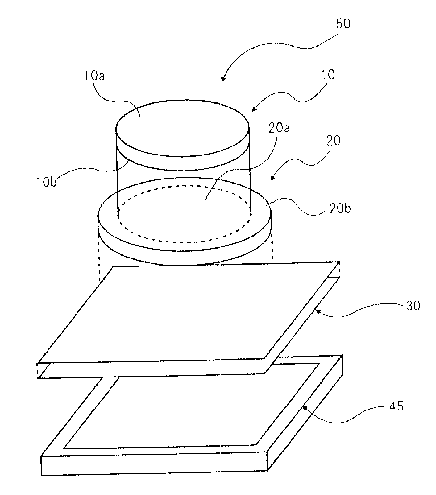
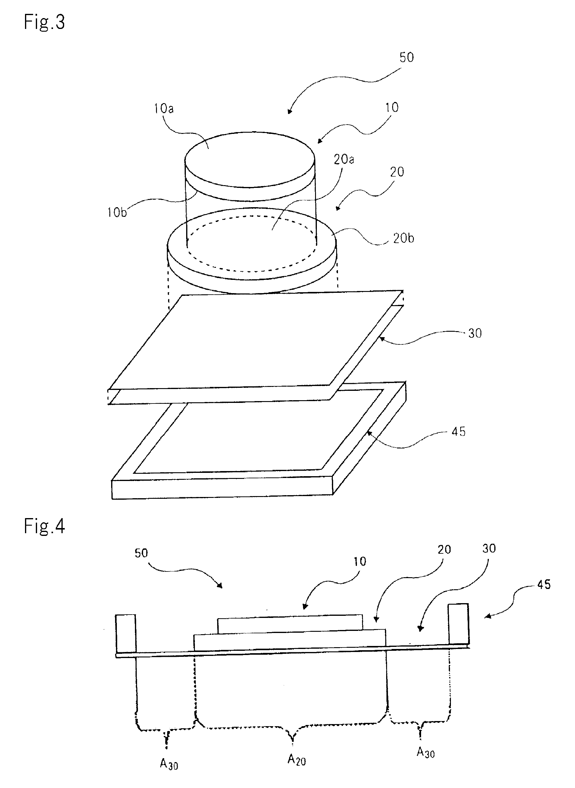
[0091]FIG. 3 is an exploded perspective view showing the configuration of the piezoelectric actuator of the present embodiment, and FIG. 4 is a vertical sectional view of the piezoelectric actuator of FIG. 3.

[0092]As shown in FIGS. 3 and 4, piezoelectric actuator 50 of the present embodiment has a configuration that includes round piezoelectric element 10 that is the drive source of vibration, base 20 for supporting piezoelectric element 10, and vibration film 30 for supporting base 20, these parts being stacked in order. Piezoelectric element 10 and base 20 are both round, vibration film 30 is square, and these three parts are arranged to have the same center (in concentric form). In addition, the outer circumference of vibration film 30 is connected to support member 45 that is formed in a square frame shape and is thus supported.

[0093]To state in greater detail, piezoelectric element 10 is composed of a piezoelectric plate (piezoelectric ceramic) having two parallel and opposite ...

second embodiment

[0116]The piezoelectric actuator of the present invention is not limited to the form shown in the above-described embodiment and may have the configuration shown in FIGS. 10A and 10B. FIG. 10A is a top view showing the configuration of the piezoelectric actuator of the second embodiment, and FIG. 10B is a vertical sectional view of the actuator. Oval-shaped support member 46c and vibration film 31c are used in piezoelectric actuator 57 of FIGS. 10A and 10B. The configuration is otherwise the same as the first embodiment. In this way, the outline shape of the support member in the present invention may be round or rectangular without any particular limitations as long as the outline shape of the piezoelectric element is different. The support member may further be a polygonal shape. In particular, when an oval support member is used, not only can sufficient vibration amplitude be obtained, but also limitations on size and shape when mounting the apparatus are relaxed by adjusting the...

third embodiment

[0117]The piezoelectric actuator of the present invention is not limited to the form shown in the above-described embodiments and may be of a configuration such as shown in FIGS. 11A and 11B. FIG. 11A is a top view showing the configuration of the piezoelectric actuator of the third embodiment, and FIG. 11B is a vertical sectional view of this actuator. In piezoelectric actuator 56 of FIGS. 11A and 11B, piezoelectric element 12 formed in a square shape and circular support member 48 are used, and piezoelectric element 12, vibration film 34, and support member 48 are components for which only the outline shapes of piezoelectric element 10, vibration film 30 and support member 45 of the first embodiment are changed, and the materials and fundamental construction are similar to the first embodiment. For example, this embodiment is identical to the above-described embodiment regarding the point that an upper electrode layer and lower electrode layer are formed on the upper and lower sur...


PUM


Abstract

Piezoelectric actuator (51) includes a piezoelectric element (11) that performs expansion / contraction movement in accordance with the state of an electrical field, a base (21) with the piezoelectric element (11) adhered to one surface thereof, and a support member (46) for supporting the piezoelectric element (11) and the base (21), the piezoelectric element (11) and base (21) vibrating up and down in accordance with the expansion / contraction movement of the piezoelectric element (11). The base (21) is connected to the support member (46) by way of a vibration film (31) having less rigidity than the base (21). In addition, the piezoelectric element (11) and support member (46) have different outline shapes.

Description

TECHNICAL FIELD[0001]The present invention relates to a piezoelectric actuator that uses a piezoelectric element to generate vibration and an electronic apparatus that uses this piezoelectric actuator.BACKGROUND ART[0002]Conventionally, electromagnetic actuators have been used as the drive source of acoustic elements such as speakers due to their ease of handling. An electromagnetic actuator is a component composed of a permanent magnet and a voice coil and that generates vibration due to the action of a magnetic circuit of a stator that uses the magnet. An electromagnetic speaker generates sound by means of vibration by a semi-rigid diaphragm such as organic film that is secured to the vibration part of the electromagnetic actuator. In recent years, the demand for compact and power-conserving electromagnetic actuators has increased with the increase in demand for portable telephones and notebook personal computers. In this regard, electromagnetic actuators are not only subject to p...

Claims


Application Information

Patent Timeline
Patent Type & Authority Applications(United States)
IPC IPC(8): H04R17/00H01L41/053H01L41/04
CPCH04R17/00H04R2499/11H04R2499/15H01L41/0973H01L41/0475H01L41/0833B06B1/0651H10N30/875H10N30/503H10N30/2047
Inventor ONISHI, YASUHARUSASAKI, YASUHIROTAKAHASHI, MASATAKEMORI, UKYOMURATA, YUKIOTOKI, NOZOMIYOKOYAMA, YUKIO
Owner NEC CORP
Why Eureka
Try Eureka