Electromagnetic field generation antenna for a transponder

Inactive Publication Date: 2010-02-18
STMICROELECTRONICS SRL
View PDF100 Cites 5 Cited by
  • Summary
  • Abstract
  • Description
  • Claims
  • Application Information

AI Technical Summary

Benefits of technology

[0011]An object of the present invention is to improve the

Problems solved by technology

A problem which arises in conventional transponder systems is that they generally have a limited range.
Now, increasing the diamet

Method used


Image

  • Electromagnetic field generation antenna for a transponder
  • Electromagnetic field generation antenna for a transponder
  • Electromagnetic field generation antenna for a transponder

Examples


Embodiment Construction

[0029]The same elements have been referred to with the same references in the different drawings. For clarity, only those elements which are necessary to the understanding of the present invention have been illustrated in the drawings and will be described hereafter. In particular, the internal structures of the electronic circuits of a transponder and of a read and / or write terminal have not been detailed.

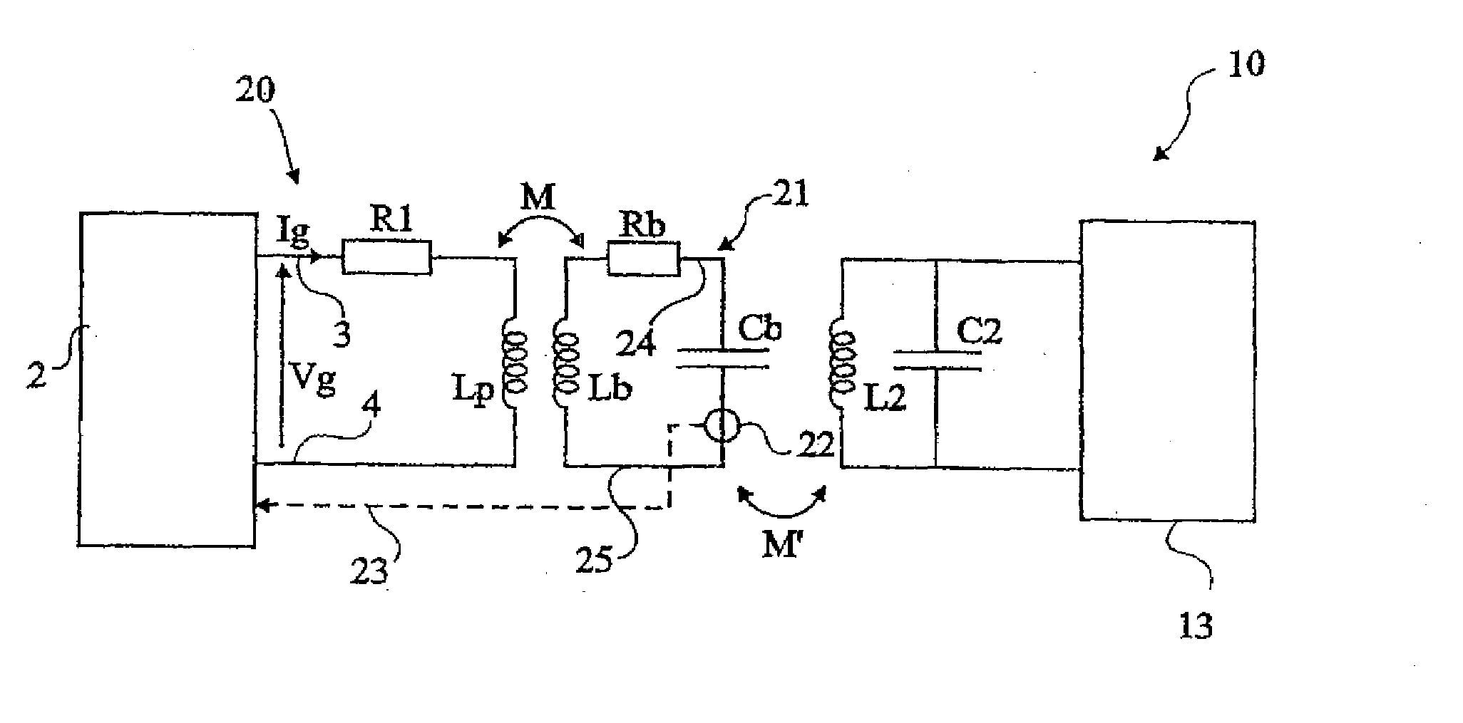
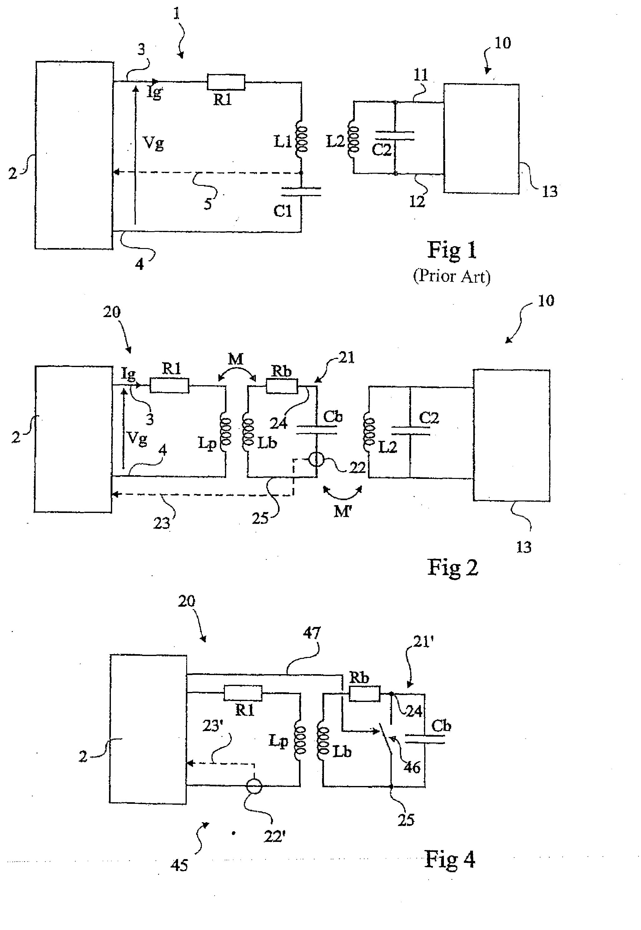
[0030]A feature of the present invention is to provide the antenna of a read and / or write terminal in the form of an LR circuit coupled to a resonant LC circuit. According to the present invention, the LR circuit is excited by the high-frequency generator of the terminal. The excitation frequency is, conventionally, that of the remote supply carrier and of the possible data to be transmitted. The resonant circuit forms a rejector circuit formed of an inductance and of a capacitor. It is in practice an RLC circuit with as small a resistance as possible corresponding to the series r...


PUM


Abstract

An antenna generating an electromagnetic field for an electromagnetic transponder and a terminal provided with such an antenna. The antenna comprises a first inductive element designed to be connected to two terminals employing an energizing voltage, and a parallel resonant circuit coupled with the first inductive element.

Description

CROSS REFERENCE TO RELATED APPLICATIONS[0001]This application is a continuation of U.S. patent application Ser. No. 10 / 344,880, filed on Feb. 14, 2003, entitled “ELECTROMAGNETIC FIELD GENERATION ANTENNA FOR A TRANSPONDER,” which application is a U.S. National Stage application of International Application serial No. PCT / FR2001 / 02621, filed on Aug. 16, 2001, entitled “ANTENNA GENERATING AN ELECTROMAGNETIC FIELD FOR TRANSPONDER,” which application claims priority benefit of French patent application number 00 / 10699, filed on Aug. 17, 2000, entitled “ANTENNA GENERATING AN ELECTROMAGNETIC FIELD FOR TRANSPONDER,” which applications are hereby incorporated by reference to the maximum extent allowable by law.BACKGROUND OF THE INVENTION[0002]1. Field of the Invention[0003]The present invention relates to systems using electromagnetic transponders, that is, transmitters and / or receivers (generally mobile) capable of being interrogated in a contactless and wireless manner by a unit (generally...

Claims


Application Information

Patent Timeline
IPC IPC(8): H01Q9/00G06K7/00G06K7/08G06K7/10
CPCG06K7/0008G06K7/10346G06K7/10336G06K7/10178
Inventor WUIDART, LUCBARDOUILLET, MICHEL
Owner STMICROELECTRONICS SRL
Why Eureka
Try Eureka