Magnetizing inrush current suppression device for transformer and control method of same

a technology of inrush current and suppression device, which is applied in the direction of relays, air-break switches, emergency protective arrangements for limiting excess voltage/current, etc., can solve the problems of inability to suppress the inrush current of magnetizing inrush which occurs to transformers of non-solid earthed systems, and the inrush current of magnetizing inrush cannot be suppressed, so as to achieve the effect of suppressing the inrush current and enlarge the circuit breaker

Active Publication Date: 2010-02-18
KK TOSHIBA
View PDF7 Cites 41 Cited by
  • Summary
  • Abstract
  • Description
  • Claims
  • Application Information

AI Technical Summary

Benefits of technology

[0019]As a result of applying this invention, a magnetizing inrush current suppression device for transformer and control method of same can be provided such that it is possible to suppress the magnetizing inrush current occurring when three s

Problems solved by technology

Therefore, such a magnetizing inrush current flows, resulting in that the system voltage fluctuates, and when this voltage fluctuation is large, consumers can be affected.
Moreover, the magnetizing inrush current suppression method in the above-described Non-patent Document 1 in which a transformer of an effectively grounded system is supplied with power by single-phase type, namely, single-phase circuit breakers, has a drawback that it is impossible to suppress the magnetizing inrush current which occurs to a transformer of a non-solidly earthed system.
Sp

Method used


Image

  • Magnetizing inrush current suppression device for transformer and control method of same
  • Magnetizing inrush current suppression device for transformer and control method of same
  • Magnetizing inrush current suppression device for transformer and control method of same

Examples


first embodiment

Other Embodiment Relevant to First Embodiment

[0101]In the above-described first embodiment, the steady-state magnetic flux calculation means 602 calculates each line-to-line steady-state magnetic flux, by converting each of the phase voltages measured by the power supply voltage measuring means 601 into line-to-line voltage, and integrating the line-to-line voltage. However, the invention includes an embodiment in which the respective phase voltages measured by the power supply voltage measuring means 601 are integrated to calculate the steady-state magnetic fluxes of respective phases, and the steady-state magnetic fluxes of respective phases are converted into line-to-line steady-state magnetic fluxes. Further, the power supply voltage measuring device 400 such as VT often has a function that converts voltages to ground into line-to-line voltages within the device, in this case, it is unnecessary to convert voltages to ground into line-to-line voltages through the steady-state mag...

second embodiment

Other Embodiment Relevant to Second Embodiment

[0124]In the second embodiment as described above, the phase detection means 605 within the switching controller for closing 600, detects the phase of the second point in time order of all points at which the obtained line-to-line steady-state magnetic flux and line-to-line residual magnetic flux have the same polarity and magnitude. However, the invention includes the following embodiment.

[0125]Specifically, when taking input, for each line-to-line (UV, VW, WU), of the output signals of the steady-state magnetic flux calculation means 602 and the output signals of the residual magnetic flux calculation means 604, the phase detection means 605, when it detects phase points at which the line-to-line steady-state magnetic flux and residual magnetic flux obtained from the signals have the same polarity and magnitude, detects all phase points or predetermined number of phase points set in advance. The closing command control means 606, from ...

third embodiment

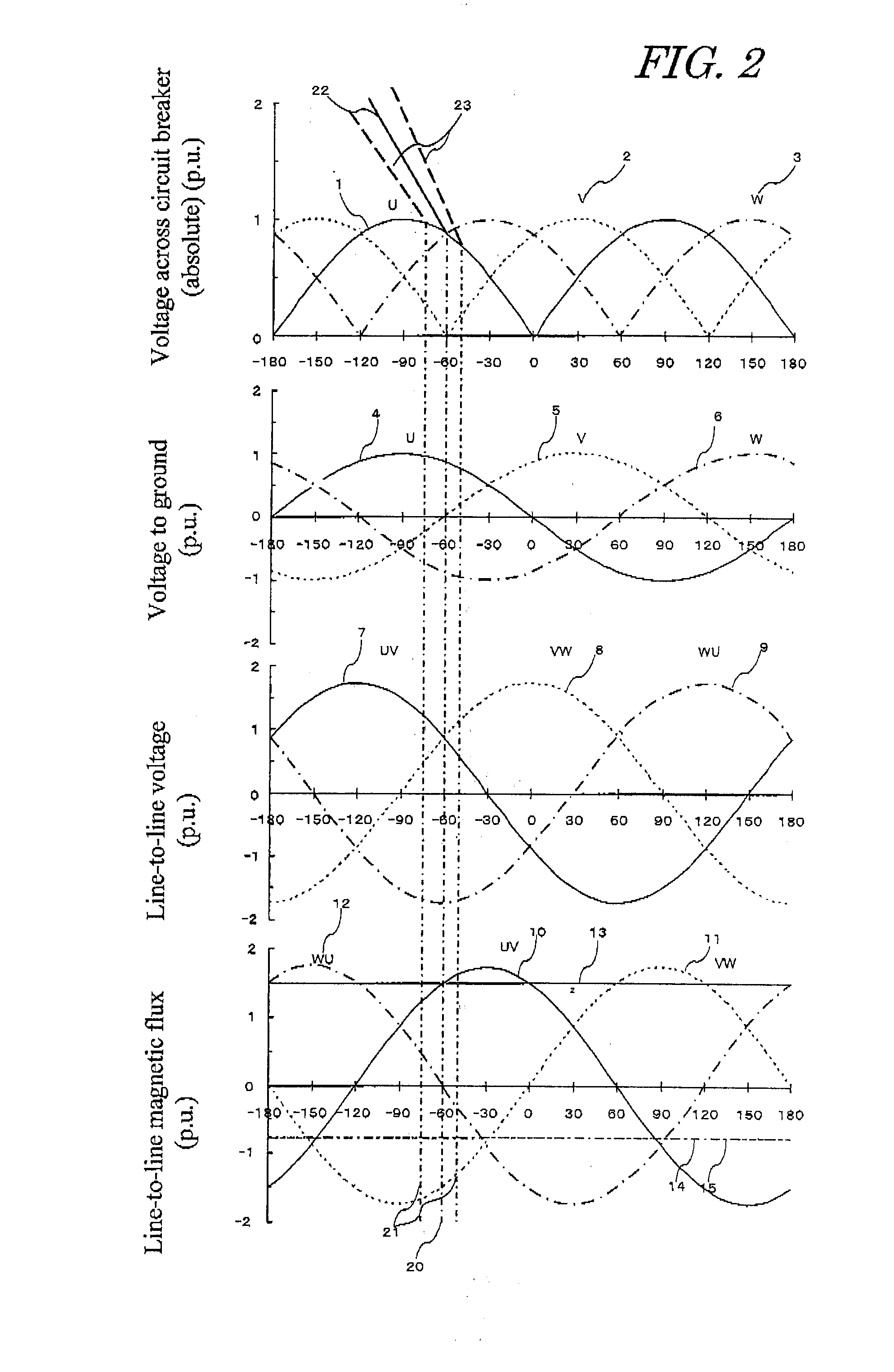
[0126]Next, a magnetizing inrush current suppression device for transformer as a third embodiment of the invention is explained below referring to FIG. 8. Here, FIG. 8 shows the phase relations between the primary Y-side phase voltages and line-to-line voltages, and the secondary or tertiary Δ-side voltages to ground and line-to-line voltages.

[Configuration]

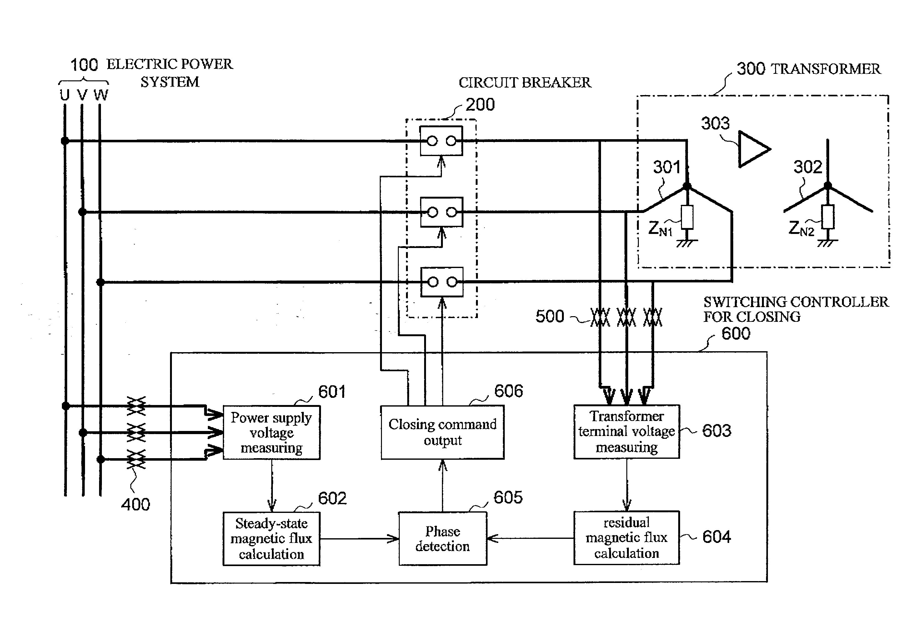
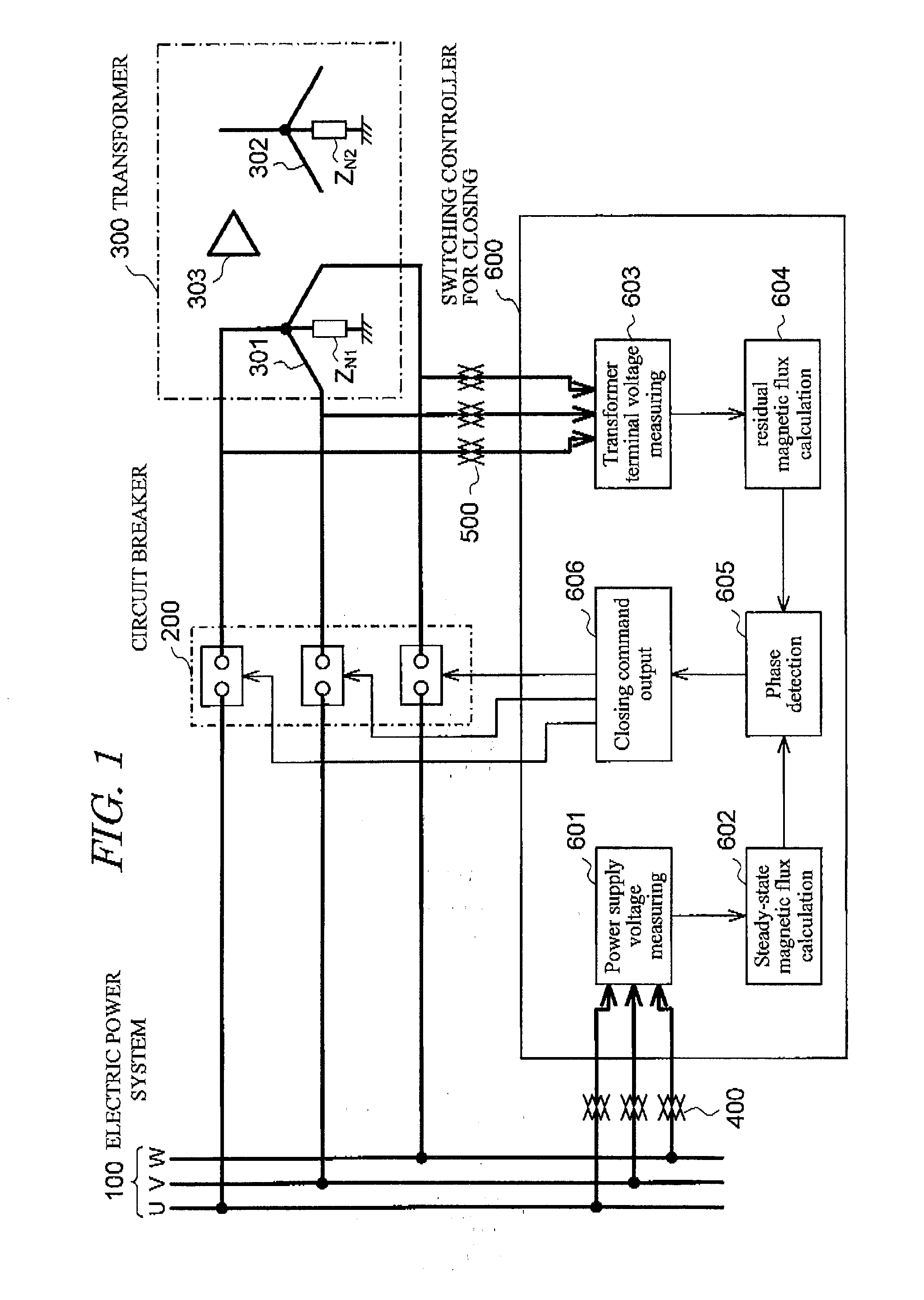
[0127]In the third embodiment, the connection relation between the three-phase transformer 300, three-phase circuit breakers 200, and switching controller for closing 600, is the same as that of the first embodiment, therefore, the third embodiment has a common configuration with the first embodiment except for the following points.

[0128]The third embodiment is a embodiment in which, even if a voltage division device is not installed on the transformer primary Y side, and the transformer terminal voltage of the primary Y side cannot be measured by the transformer terminal voltage measuring means 603 through the transformer termin...


PUM


Abstract

To provide a magnetizing inrush current suppression device for transformer and control method of same, which accurately calculates the residual magnetic flux when a transformer installed in a non-solidly earthed system, is interrupted by circuit breakers, and which enables suppression of the magnetizing inrush current occurring when three single-phase circuit breakers or single-phase circuit breakers are used for simultaneously supplying power to three phases of the transformer, without providing a circuit breaker with a resistor or other equipment to enlarge the circuit breaker. The device has steady-state magnetic flux calculation means for calculating the line-to-line steady-state magnetic flux of three-phase power supplies, residual magnetic flux calculation means for calculating the primary line-to-line residual magnetic flux of the transformer when the circuit breakers interrupt the transformer, phase detection means for detecting a phase at which the polarity and magnitude of the calculated steady-state magnetic flux and residual magnetic flux coincide for each line-to-line. Closing control means firstly causes only two-phase of the circuit breakers, which are connected with the line-to-line, to close at the detected phase, and then causes the remaining one-phase circuit breaker to close.

Description

TECHNICAL FIELD[0001]This invention relates to a magnetizing inrush current suppression technique for suppressing the magnetizing inrush current which occurs when a power supply is input to a transformer, especially to a magnetizing inrush current suppression device for transformer and control method of same, which accurately calculate the residual magnetic flux and enable suppression of the magnetizing inrush current without providing a circuit breaker with a resistor or other equipment.BACKGROUND ART[0002]When no-load energizing is performed by supplying power to a transformer in a state in which there is residual magnetic flux in the transformer core, a large magnetizing inrush current may flow. Generally, the magnitude of this magnetizing inrush current can be greater than or equal to several times the rated load current of the transformer. Therefore, such a magnetizing inrush current flows, resulting in that the system voltage fluctuates, and when this voltage fluctuation is la...

Claims


Application Information

Patent Timeline
IPC IPC(8): H02H7/04
CPCH02H9/002
Inventor KOSHIZUKA, TADASHISAITO, MINORUFUTAGAMI, KOICHIKUSUYAMA, HIROSHISATO, YOSHIMASA
Owner KK TOSHIBA
Why Eureka
Try Eureka