Pneumatic presssure wedge

a technology of pneumatic presssure and wedge, which is applied in the direction of cooling/ventilation/heating modifications, electrical equipment, electrical apparatus contruction details, etc., can solve the problems of many conventional cooling methods not being utilized for trimming, generating additional heat, and insufficient cooling of edge mounted configurations

Inactive Publication Date: 2010-02-18
RAYTHEON CO
View PDF20 Cites 32 Cited by
  • Summary
  • Abstract
  • Description
  • Claims
  • Application Information

AI Technical Summary

Benefits of technology

[0013]It is a further object of this inventi...

Problems solved by technology

There is a tendency to drive the microwave integrated circuitry at higher and higher power levels which generates additional heat.
At the same time, many conventional cooling methods cannot be utilized for the TRIMM because they must be easily and quickly removed from their respective equipment racks for servicing.
Studies have shown that at higher power levels the edge mounted configuration may not provide sufficient cooling.
With higher power levels, however, flange cooling may not be sufficient in such a design.
But, fasteners are undesirable because of the time required to install and remove a TRIMM from its heat sink.
Fasteners also do not ensure sufficient heat transfer since good contac...

Method used


Image

  • Pneumatic presssure wedge
  • Pneumatic presssure wedge
  • Pneumatic presssure wedge

Examples


Embodiment Construction

[0037]Aside from the preferred embodiment or embodiments disclosed below, this invention is capable of other embodiments and of being practiced or being carried out in various ways. Thus, it is to be understood that the invention is not limited in its application to the details of construction and the arrangements of components set forth in the following description or illustrated in the drawings. If only one embodiment is described herein, the claims hereof are not to be limited to that embodiment. Moreover, the claims hereof are not to be read restrictively unless there is clear and convincing evidence manifesting a certain exclusion, restriction, or disclaimer.

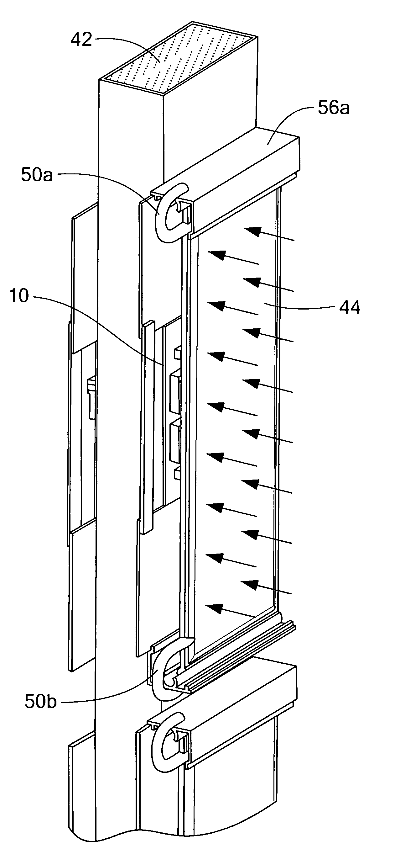
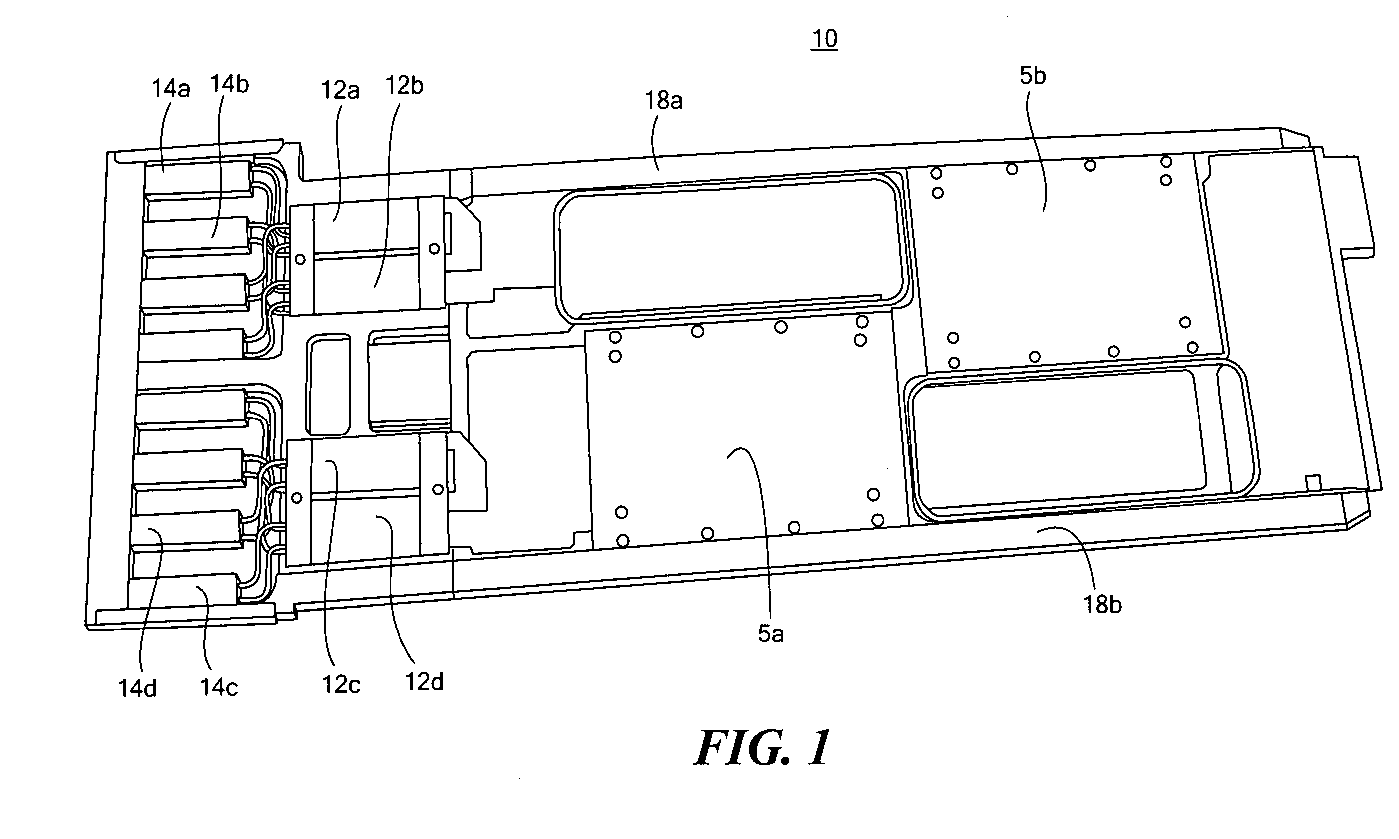
[0038]FIG. 1 shows electronics module 10 in accordance with an example associated with the subject invention. In this example, module 10 is a radar transmit and receive integrated microwave module or “TRIMM” with transmit / receive units 12a-12d, polarizers 14a-14d, and power supplies (DC / DC converters) 5a and 5b.

[0039]In th...


PUM


Abstract

An electronic subsystem such as an array of radar transmit/receive microwave modules are associated with (e.g., base mounted to) spaced heat sinks. There is an electronic module on each side of each heat sink and an inflatable bladder or “pneumatic pressure wedge” between adjacent heat sinks biases a pair of electronic modules against their respective heat sinks.

Description

FIELD OF THE INVENTION[0001]The subject invention relates to cooling electronic modules which, in one particular example, are radar transmit / receive integrated microwave modules.BACKGROUND OF THE INVENTION[0002]Electronic circuits are traditionally cooled using a variety of methods. In certain radar systems, there are hundreds of electronic modules called transmit / receive integrated microwave modules (TRIMMs). Each such module includes several transmit / receive units, polarizers, and power supplies between spaced side rails which are cooled via coolant flowing in manifold ribs in an equipment rack housing the modules.[0003]There is a tendency to drive the microwave integrated circuitry at higher and higher power levels which generates additional heat. See co-pending U.S. patent application Ser. No. 11 / 716,864 filed Mar. 12, 2007 incorporated herein by this reference. At the same time, many conventional cooling methods cannot be utilized for the TRIMM because they must be easily and q...

Claims


Application Information

Patent Timeline
IPC IPC(8): H05K7/20
CPCH05K7/20636H05K7/2049
Inventor DANELLO, PAUL A.MARTINEZ, MICHAEL P.BELANGER, RUSSELL D.BENTO, JOAQUIM A.ELLSWORTH, JOSEPH R.
Owner RAYTHEON CO
Why Eureka
Try Eureka