Focus ring, plasma processing apparatus and plasma processing method

Inactive Publication Date: 2010-02-18
TOKYO ELECTRON LTD
View PDF7 Cites 8 Cited by
  • Summary
  • Abstract
  • Description
  • Claims
  • Application Information

AI Technical Summary

Benefits of technology

[0006]In view of the above, the present invention provides a focus ring, a plasma processing apparatus and a plasma processing method, wherein the service lif

Problems solved by technology

However, such replacement of the focus ring causes deterioration of operat

Method used


Image

  • Focus ring, plasma processing apparatus and plasma processing method
  • Focus ring, plasma processing apparatus and plasma processing method
  • Focus ring, plasma processing apparatus and plasma processing method

Examples


Embodiment Construction

[0016]Hereinafter, a focus ring, a plasma processing apparatus and a plasma processing method in accordance with embodiments of the present invention will be described in detail with reference to the accompanying drawings which form a part hereof.

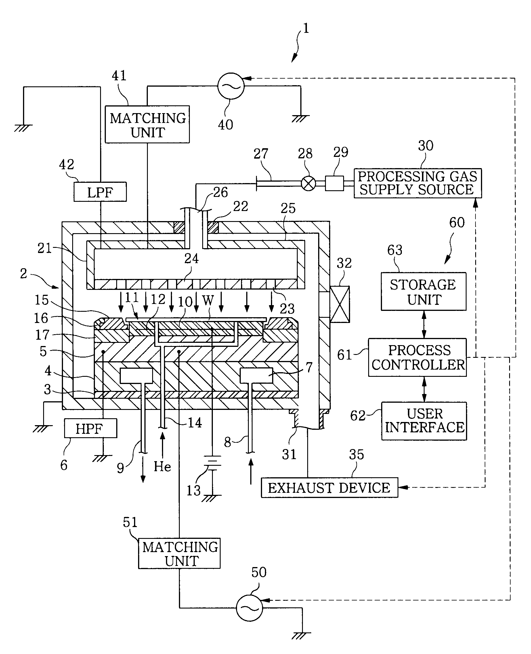
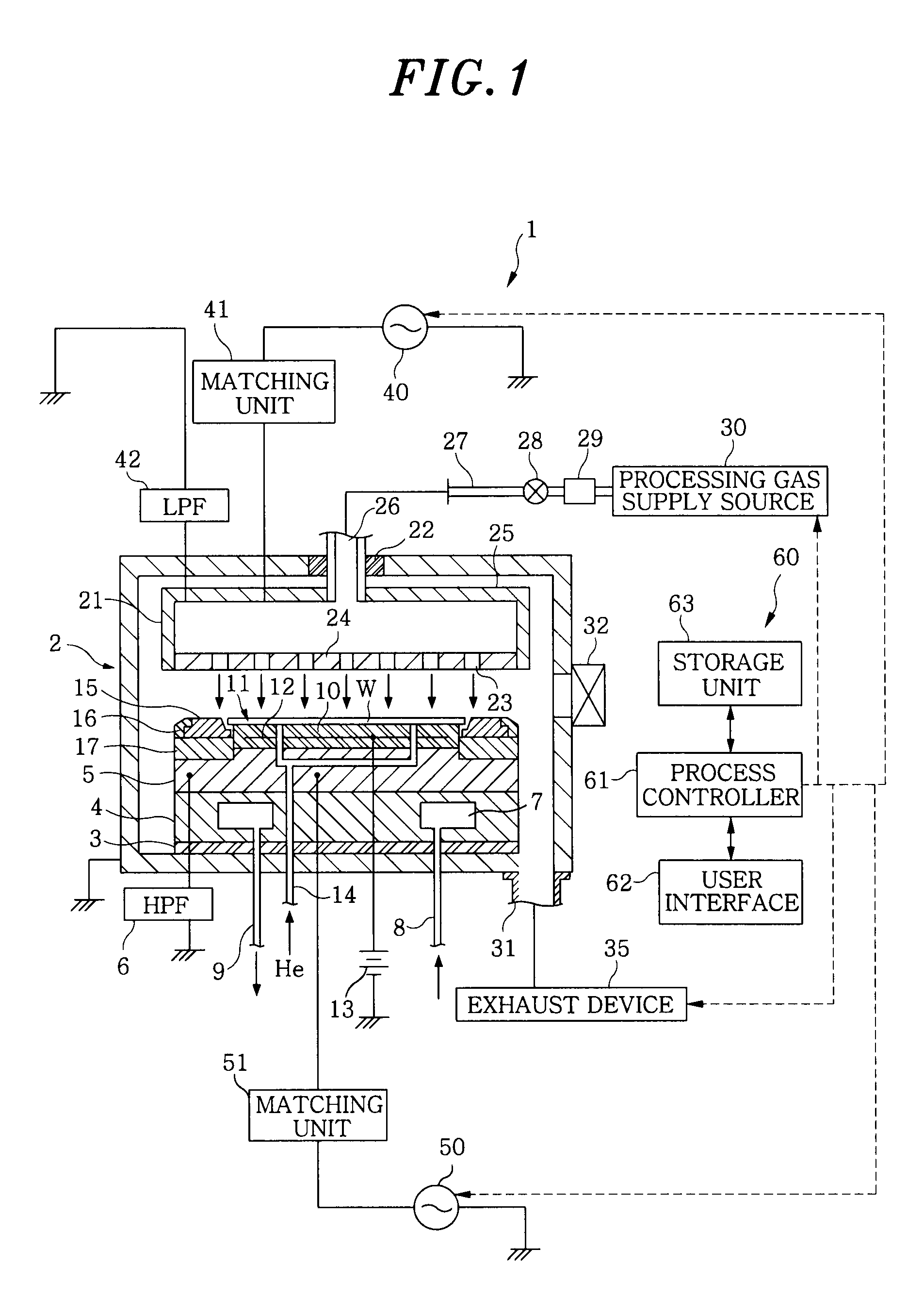
[0017]FIG. 1 is a view showing a general configuration of a plasma etching apparatus 1 as a plasma processing apparatus in accordance with one embodiment of the present invention, and FIG. 2 is a view showing main parts of a focus ring 15 and the plasma etching apparatus 1 in accordance with the embodiment of the present invention. First, the general configuration of the plasma etching apparatus 1 will be described with reference to FIG. 1.

[0018]The plasma etching apparatus 1 is configured as a capacitively coupled parallel plate type etching apparatus in which an upper and a lower electrode plate are disposed opposite to each other in parallel and power supplies for generation of plasma are connected to the electrode plates, respectively.

[...


PUM

PropertyMeasurementUnit
Lengthaaaaaaaaaa
Distanceaaaaaaaaaa
Distanceaaaaaaaaaa

Abstract

A focus ring of a ring shape is disposed to surround a target substrate on a lower electrode on which the target substrate is mounted in a process chamber. The process chamber receives the target substrate and subjects the received target substrate to a plasma process. At the point of time when the focus ring is first used for the plasma process, a distance between a lower side of an edge portion of the target substrate and a portion of the focus ring facing the lower side of the edge portion of the target substrate is set to be equal to or greater than about 0.4 mm.

Description

FIELD OF THE INVENTION[0001]The present invention relates to a focus ring, a plasma processing apparatus and a plasma processing method.BACKGROUND OF THE INVENTION[0002]Conventionally, in the field of manufacture of semiconductor devices, there are known plasma processing apparatuses for plasmarizing a process gas and subjecting a target substrate, e.g., a semiconductor wafer or a glass substrate for LCD, to a specified process, e.g., an etching process or a film forming process.[0003]In the above-mentioned plasma processing apparatuses, for example, plasma processing apparatuses for performing a plasma etching process on a semiconductor wafer, it has been known to provide a focus ring around the semiconductor wafer mounted on a lower electrode to increase uniformity of plasma processing in a plane of the semiconductor wafer (for example, see Japanese Patent Application Publication Nos. 2008-078208 and 2003-229408 and U.S. Patent Application Publication Nos. 2008 / 66868A1 and 2005 / 58...

Claims


Application Information

Patent Timeline
IPC IPC(8): H01L21/30C23C16/54H01L21/3065
CPCH01J37/32642H01L21/3065H01L21/683
Inventor TSUJIMOTO, HIROSHINAGAIWA, TOSHIFUMIHANDA, TATSUYA
Owner TOKYO ELECTRON LTD
Why Eureka
Try Eureka