
Expeditionary pod construction

a technology of expansion pods and pod assemblies, applied in the field of expansion pods, can solve the problems of limited true transportability of such a structure, and no one design generally addresses all the problems,

Inactive Publication Date: 2010-02-25
STRATEGIC SOLUTIONS UNLTD
View PDF8 Cites 49 Cited by
  • Summary
  • Abstract
  • Description
  • Claims
  • Application Information

AI Technical Summary

Benefits of technology

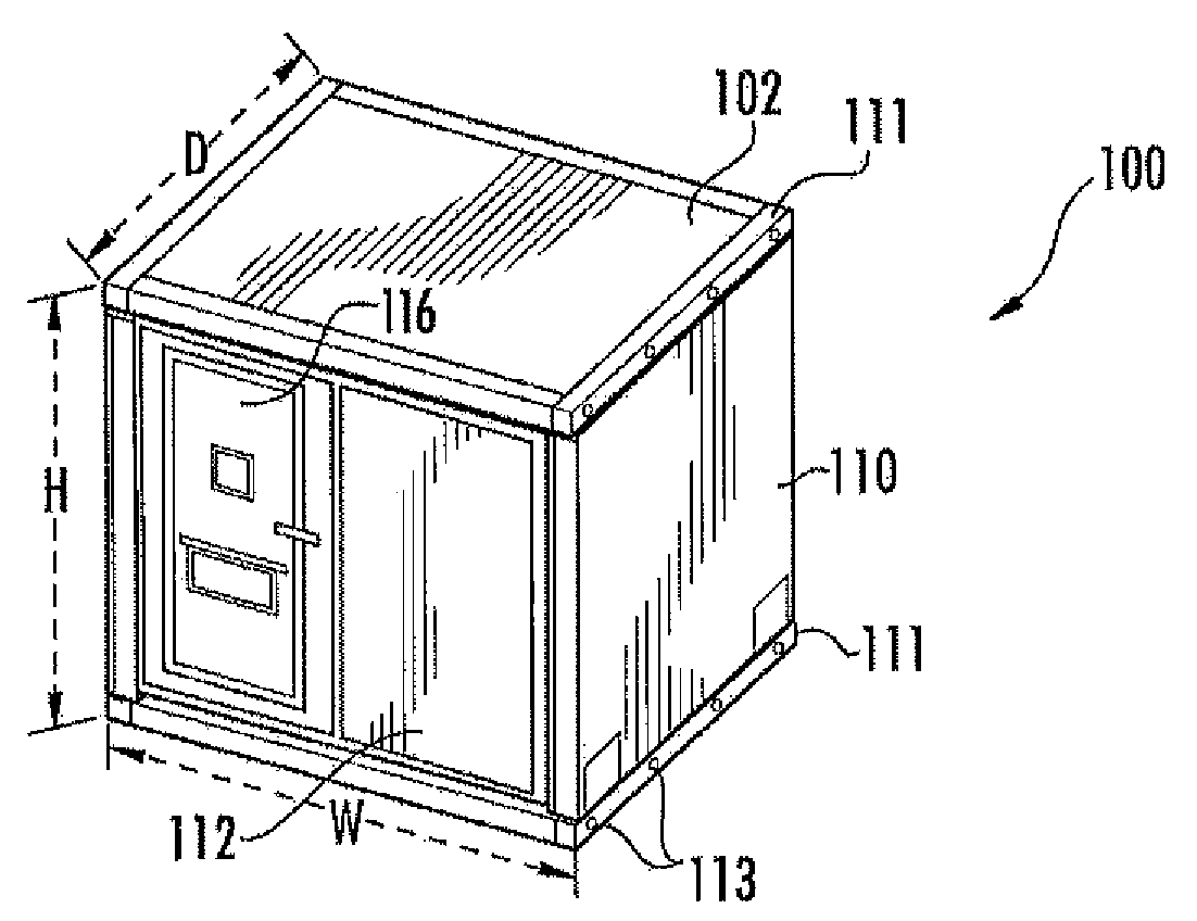
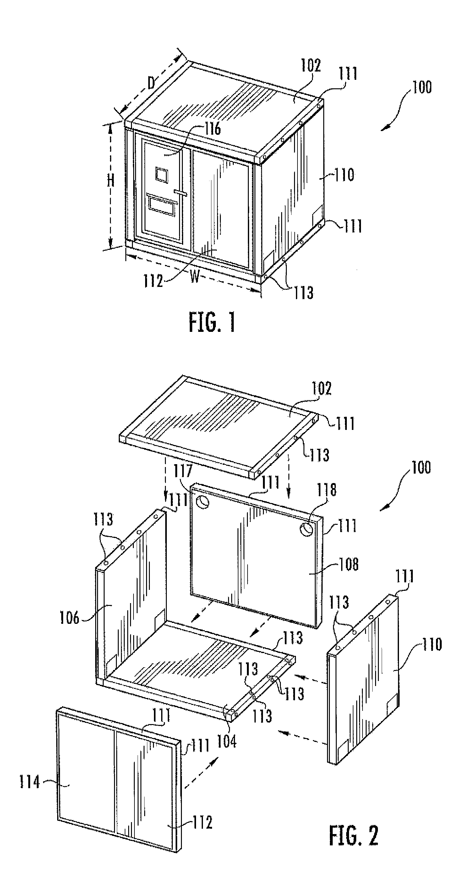
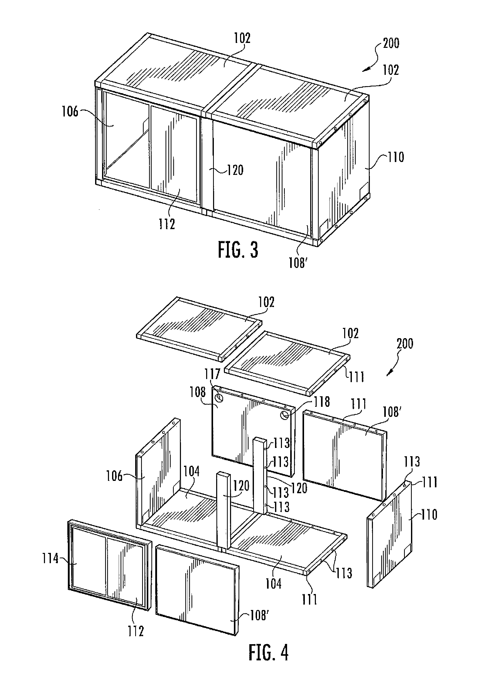
[0007]The presently disclosed features and others associated with the subject modular pod assemblies result in a highly secure and temporary space for living, working or storage in remote, austere and demanding environments that can be quickly assembled on location. Units may be disassembled and reconfigured in multiple configurations resulting in different shapes and / or sizes. Once assembled, pods are structurally capable of being stacked one on top of the other to form a stacked assembly of multiple units. One exemplary disassembled embodiment may be adapted for rapid delivery and mission support via the standard 108″×88″ (463L) air cargo pallet system used by the U.S. military. Such an exemplary disassembled modular pod may weigh about 1000-1500 pounds and stand between about 36-42 inches high on a standard pallet, such that two disassembled pods can easily fit on one pallet. The resultant fully transportable, high security custom buildings can advantageously provide a variety of different uses, including but not limited to sound proof interview rooms, showers, sleeping quarters, work areas, etc.

Problems solved by technology

The true transportability of such a structure is limited when it is not easily disassembled or movable after initial assembly.
While various aspects and alternative features are known in the construction field, no one design has emerged that generally addresses all of the issues as discussed herein.

Method used


Image

  • Expeditionary pod construction
  • Expeditionary pod construction
  • Expeditionary pod construction

Examples


Embodiment Construction

[0028]As discussed in the Summary of the Invention section, the present subject matter is particularly concerned with modular pod or housing assemblies, and more particularly to a transportable and easily configured high security assembly of modular panels. Selected combinations of aspects of the disclosed technology correspond to a plurality of different embodiments of the present subject matter. It should be noted that each of the exemplary embodiments presented and discussed herein should not insinuate limitations of the present subject matter. Features or steps illustrated or described as part of one embodiment may be used in combination with aspects of another embodiment to yield yet further embodiments. Additionally, certain features may be interchanged with similar devices or features not expressly mentioned which perform the same or similar function.

[0029]Reference will now be made in detail to the presently preferred embodiments of the subject modular pod assemblies. Referr...


PUM

PropertyMeasurementUnit
heightaaaaaaaaaa
heightaaaaaaaaaa
heightaaaaaaaaaa

Abstract

A modular pod assembly capable of being readily assembled and disassembled for transportation includes a plurality of modular panels and a plurality of connectors. Each said modular panel includes a rigid and substantially planar structure delimited along one or more edges by respective coupling portions, each coupling portion formed to define a plurality of preconfigured access points for receiving respective connectors. Multiple connectors are provided to securely fasten a coupling portion of a given modular panel to a coupling portion of another adjacent modular panel at a selected access point. The plurality of modular panels may be provided in an assembled state to include at least one top panel, bottom panel, and a plurality of respective side walls, all securely fastened together at respective coupling portions with the plurality of connectors to form an integrated enclosure.

Description

PRIORITY CLAIM[0001]This application claims the benefit of U.S. Provisional Patent Application No. 61 / 189,465 filed Aug. 20, 2008, entitled “EXPEDITIONARY POD CONSTRUCTION” and having the same inventors as present, which is incorporated herein by reference for all purposes.FIELD OF THE INVENTION[0002]The present subject matter generally relates to modular pod assemblies, and more particularly to transportable and easily configured high security building assemblies of modular panels.BACKGROUND OF THE INVENTION[0003]Portable buildings are useful in a variety of potential environments, including but not limited to storage facilities, temporary housing, and the like. Most such structures are configured for a single occurrence of assembly and / or placement, at which point the structure remains intact or in its assembled location. The true transportability of such a structure is limited when it is not easily disassembled or movable after initial assembly. As such, a need exists for constru...

Claims


Application Information

Patent Timeline
Patent Type & Authority Applications(United States)
IPC IPC(8): E04H1/02E04H1/12E04B1/38E04C2/52E04C2/20
CPCE03C1/01E04B2001/34389E04B1/6183E04B1/34321E04B1/34317
Inventor MARTIN, TONY M.PLEASANTS, DONALD A.
Owner STRATEGIC SOLUTIONS UNLTD
Learn More